The Tunnel
For further simplification of the model the tunnel will be designed along an exemplary path and will consist of the space describing the bored cave, the structural tunnel hull (Tübbing Elements) as well as the filling between the bored cave and the tunnel hull. Keeping it that simple enables the model to be optimized in regard of building resources and costs per tunnel meter.
![Figure 1: Tübbing construction design [Tunnelbau Script TU Berlin]](http://130.149.22.198/wp/wp-content/uploads/2020/02/Tübbing.jpg)
The here displayed tunnel is drilled with a Tunnel Boring Machine and constructed with Tübbing elements as it is part of an airport assembly unit. Its main purpose is to ensure unhindered delivery of assembly parts needed at the hangar. While this could also take place via the airfield, a tunnel provides infrastructure that won’t cause any problems or delays of the air traffic.
Ontology
The initial ontology was focusing on shapes, internal interfaces and different construction methods. To focus on the system integration this ontology was narrowed down and only includes the essential tunnel parts like its axes and elements that build a basic circular Tübbing tunnel.
Parametric Modelled Tunnel
With the help of design parameters and high-performance criteria (HPC), different model alternatives can be developed. While defining parameters for the tunnel model, focus lied on dependencies between the structural tunnel body and its location. To keep it simple, the tunnel axes runs through three points in the Cartesian coordinate system. While the end point is fixed -5.0m under the center of the hangar the starting point is adjustable but fixed at the coordinates [-1000,-1000,-10], which is on the other side of the runway. The middle coordinate was changeable and worked as an input parameter for the generative design used later on. Other parameters like tunnel radius and Tübbing size are also changeable, but weren’t considered in the collaborative product modelling.
That’s why the path the tunnel takes will look straight and not very deep under ground. When adding linear buildings like landing stripes, the tunnel construction might be more efficient material wise. A path around or deep under the building are possible alternatives.
While the tunnel checks for other buildings above the tunnel axes it also reads the tunnel Depth above the drilled tunnel. Both this information eventually adds thickness to the initial Tübbing ring size. Right now those added values are kept pretty simple, but could adapted pretty easily.
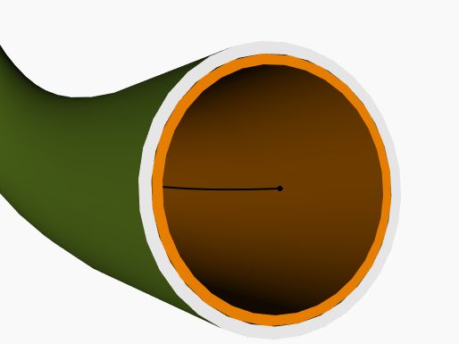
Figure 2 displays the modeled tunnel with its three layers of the void bored tunnel cave (green), the Tübbing elements (orange) and the mortar filling (grey).
Challenge
The challenge or rather the beneficial use of such a basic tunnel model is the information you can get on how much material is used in relation of the tunnel location and length. A model like this could enable fast and easy feasibility studies on tunnel planning through built-up areas like city’s.
Download: tunnel_model & tunnel_ontology.
Also check out the single models of the hangar and the runway!