Introduction
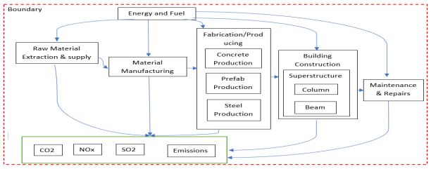
To do an life-cycle analysis, which was followed by an multi-criteria optimization the goal was to conduct a carbon footprint analysis, so the major factors associated with the selected model of Beam of a RCC building structure are it’s materials requirement for construction which in turn have an impact on carbon footprint. The scope ranged from the raw materials extraction till it’s usage and finally till maintenance and repairs. So, while these processes take place step by step, we needed to take into account the harmful effect on our environment caused by this. So we choosed, the following scope and boundary of our analysis. Different gases, their required energy quantity are analyzed and main gases such as CO2, SO2 and NOx are taken into account and how much emissions these exude helped us in achieving our goal of conducting the carbon footprint analysis. The boundary of the analysed system can be seen in the figure below.
Lice-Cycle Analysis & Multi-Criteria Decision Making
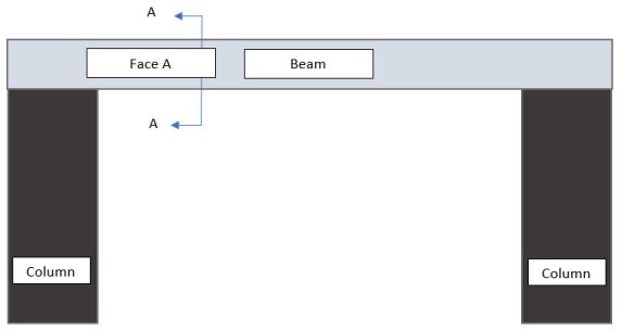
To understand the construction better there was a model established of how the struture will loke like, as presented in figure 2.4.2 below.
Based on figure 2.3.2 the design alternatives, which are presented in table 2.4.1, vary in the materials being used.
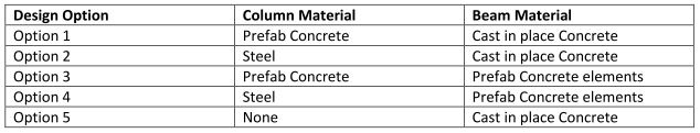
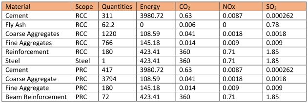
The materials being used for the design options, can be seen in table 2.4.2.
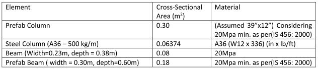
The following table 2.4.3 presents the composition of different materials used.
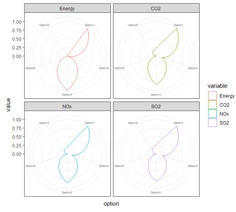
Based on the information presented so far and the intervention strategy the results of the life-cycle analysis are presented in form of radar plots, which can be seen in figure 2.4.3 below.
In addition by adding weights for the different criterias intruduced, to set the calculation matrix in the RCode the results of the multi-criteria decision making analysis are presented in figure 2.4.4
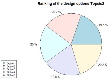
The figure 2.4.4 showed that each of the discussed design alternatives are pretty close in value to each other.