1. Abstract:
In this study the ontology that has been developed in the first phase of the project is used as capita-selecta and the parametric model here is assumed to be used at an early phase of the office building design for rapid design making regarding project, as it has been stressed by Goia, this process is lacked in the first phases of the project. With this study it has been aimed to address this issue by developing and creating parametric model with strong parametric control on diverse geometrical properties of a one-story office building. The model had been evaluated with respect to two high-performance criteria: Optimum Total energy consumption by Window-to-wall ratio (WWR) and sufficient acoustic comfort by Sound Transmission Loss (STL).
2. Scope and High-Performance Criteria(HPC):
The parametrically modelled one-storey co-working office building is located in Oslo, Norway. An optimum WWR ratio for an ideal total energy consumption lies between 0.30 and 0.45 [3]. In terms of onset privacy, the STL level should be at least 40 dB[8].
- Optimum total energy consumption is addressed by calculating the WWR (Figure 1, Eq. 2)
- Equation 3 represents the total energy consumption that Goia et al. considered throughout the research and HPC was checked according to the Oslo(WWR-E_tot, Fig. 1)
- Acoustic comfort is addressed by calculating the compsite sound tranmission loss (Eq. 3) of the façade, which means considering different building components such as (glass, aluminum, brick etc.)

Fig.1: HPC Equations.
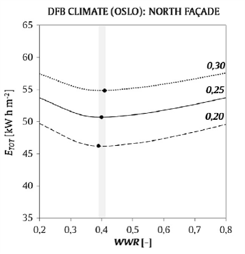
Fig.2: Oslo Dfb: ETOT(WWR) for different SA:V values -North Orientation (Goia, 2016)
3. Logic of the parametric model:
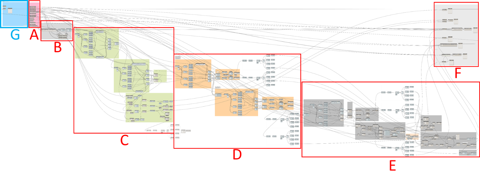
Fig.3: Dynamo Workspace, A: Input, B: domain creation, C: Wate Flow Glazing facade Unit and Aluminium Panels, D: Brick Wall, E: Concrete Side Walls, Back Wall, Roof and Floor creation, F: parameters for calculation performance indicators, G: performance indicators.
The parametric model had been created by using Dynamo, version 2.12. The workflow of the parametric model can be seen in Fig. 3(A-G). Part A stands for Input parametes and Part G stands for output/performance criteria indicators. Throughout the creation process of the one-story co-working office building, having good control on the parameters that influence performance criteria are prioritized. As it has been mentioned before WWR and STL are two conflicting requirements that needed to be balanced through the design according to the optimum requirements. Therefore, for making this control easy and more conceivable Maximum Total Length of the WFG façade system is parametrized and if the selected total length of the WFG system is lower then its maximum, a brick wall is replaced (Fig. 6). Followingly, if there is a reduction on the height of the glazing is replaced by its aluminum panel. For the boundry conditions of the WFG modular unit, the ontology that was created in the first project assignment is used WFGDesign_Ontology. Replaced brick wall can be seen in Fig. 5 on the sides of the WFG system in light yellow color. Their calculations are clearly done on Dynamo individualassignment_2 Furthermore, additional, brick wall section is parametrized on the edges of the facade in case of more area needed for optimum STL. The office building is dimensioned by using tool that calculates the required meter square per person and the neccesary functional areas taken from the Norwegian Labour Inspection Authority. One-story office building is designed for 5 people and throughout the parametric model it has kept constant. Total Height of the building has also been kept constant.
4. Discussing design alternatives:
In Fig. 5 the three main design options can be seen. Although they are geometrically different, all of them satisfies the abovementioned high-performance criteria. For instance Design option “a” has usable floor area of 58m2 with a 0.353 WWR ratio which corresponds to a nearly 60 kWhm2 total energy consumption. This WWR ratio is highest among the others as it has designed to have ideal WWR ratio. STL value of “a” obtained 40.18 dB which lies beneath the required level of transmission loss. Design option “c” distinguishes itself by having total length greater than its width which allows this design to satisfiy STL parametrically quicker than others as it is greater in brick wall area in the façade with having 0.30 WWR ratio which intersects with the above optimal level of the curve by having an energy consumption in between 55-60 kWhm2. These designs can be repeated for visualizing basic geometrical properties in the model by arranging the input values for a) Building Width: 12.5, Brick Wall Length: 0.5, Glass Heigth: 1.61, Glass Width: 0.74, Number of WFG unit per facade:3 b) Building Widt: 9, Brick Wall Length: 0.44, Glass Heigth: 1.3, Glass Width: 0.74, Number of WFG unit per facade:5 c) Building Width: 4.5, Brick Wall Length: 3.57, Glass Heigth: 1.33, Glass Width: 0.91, Number of WFG unit per facade:8. Finally, design option “b” distinguishes itself by having the least WWR with 0.29 and also the least total energy consumption. In conclusion, as it can be seen through the modelling, with a pre-determined floor area buildings’ compactness lies very close in between designs, respectively, 2.51, 2.14, 2.93.
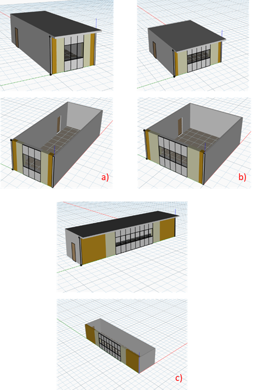
Fig.1: The divided categories of timber formwork uses.
Individual_Model by erencav on Sketchfab
References
- [1] Durmisevic, Sanja & Marradi, Benedetta. (2016). Calculation and analytical methods for building components. Deliverable report 1.4, INSITER.
- [2] DiRoots, Dynamo Basic Training, (2018). youtube.com/c/DiRootsNews
- [3]Goia, Francesco. (2016). Search for the optimal window-to-wall ratio in office buildings in different European climates and the implications on total energy saving potential. Solar Energy. 132. 467–492. 10.1016/j.solener.2016.03.031.
- [4] Peel, Murray & Finlayson, Brian & Mcmahon, Thomas. (2007). Updated World Map of the Koppen-Geiger Climate Classification. Hydrology and Earth System Sciences Discussions. 4. 10.5194/hess-11-1633-2007.
- [5] InDeWag, Water Flow Glazing Systems, Façade Manual, indewag.eu/manuals.php
- [6] Ungureanu, L, Bridge Tutorial, Parametric model generation with Dynamo.
- [7] https://skepp.com/en/blog/office-tips/this-is-how-many-square-meters-of-office-space-you-need-per-person#calculator
- [8] Lamancusa, J. S. (2000). Transmission of Sound Through Structures. Penn State.
- [9] STC Ratings for Windows, Triple-Pane Glass bettersoundproofing.com/stc-ratings-for-windows/
- [10] The Norwegian Labour Inspection Authority. (2012) Regulations concerning the design and layout of workplaces and work premises (the Workplace Regulations).
One-storey Co-working Office Building:
To the Water Flow Glazing Façade Systems Ontological Modelling: