Defining the Parametric Model
The project involves a steel structure for factories given fixed design (fixed sections), width and length, while affording adaptability in eave and ridge height specifications. The primary objective of the model centers on quantifying the fluctuation in construction costs contingent upon variations in the structural height. The computation of construction costs predominantly relies upon the assessment of the structural frame’s weight.
Design Parameters
- Fixed:
- Width (span) = 10m
- Spacing = 7m
- Number of frames = 8
- Length of the structure (Spacing * number of frames)
- Number of purlins (one side) = 5
- Variable:
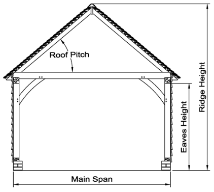
- Height: this is the eave height of the structure, as it depends only on the height of the column.
- Roof slope: the ridge height doesn’t only depend on the column height, but also the slope of the roof.
High Performance criteria
In this model we will be trying to reach a specific ridge height = 8 m with the lowest possible steel weight and the lowest construction cost. Changing or increasing the ridge height depends on the eave height and the roof slope. Increasing the eave (column) height will increase the total weight of the structure by increasing the weight of columns and increasing the number of sides rails, as for every 1 m in height, a rail must be added. On the other hand, increasing the roof slope will increase the length of the rafter and roof bracings, leading to weight increase.[1]
Importance of the ridge height in steel structured factories
- The ridge height is often designed to provide sufficient clearance for machinery, equipment, or any other installations within the building. It ensures that these elements can operate effectively without constraints.
- The ridge height can impact natural lighting and ventilation within the structure. Design considerations related to energy efficiency and occupant comfort may influence decisions about the height of the ridges.
- The model aids in designing a cost-effective structure by minimizing excess material usage. Instead of a one-size-fits-all approach, the structure can be tailored to meet the specific needs of the manufacturing processes, potentially reducing construction costs.
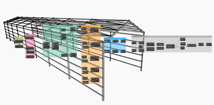
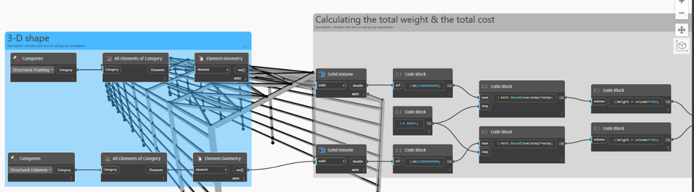
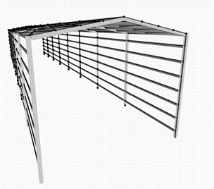
Description of the model
I installed a dynamo package called “structural design” that has steel structure sections already defined.
1.Defining the design parameters: We specified the parameters as outlined earlier.
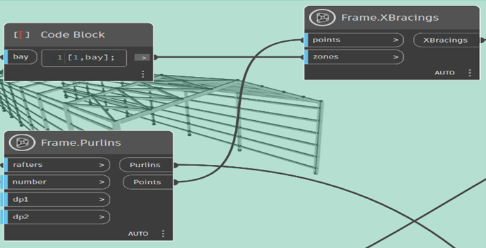
2.Defining the structural elements: Such as columns, beams, purlins, roof bracing and side girts. For roof bracing there is no need for it every bay, just the first and last one. For this we added a code block as an input to the zone of X-bracing.
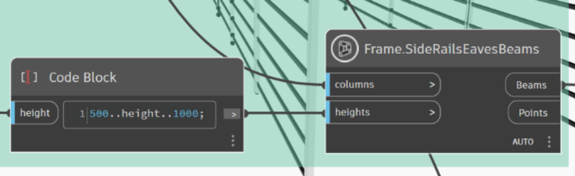
For the side rails, we maintained 1 m distance between each one except the upper first one, 50 cm from the frame, also we need the number of girts to be automatically linked with the column height. For this, we added a code block as an input for the height of the side rails.
3.Defining the section types for each structural element: For this part, we assumed the steel sections for each structural element (fixed design), as the purpose of the project is not structural analysis. We just need some reasonable sections in order to calculate the weight of the building and also the construction cost.
4.Calculating the weight and the construction cost of the structure: First, we got the volume of the frame elements and the columns, then we multiplied the volume by the density of these elements (7900 kg/m3) to get the weight. Then we multiplied the total weight by the price per unit weight to get the total construction cost.
Construction cost in this model is calculated as material cost + labor cost. Material cost (based on a certain supplier) = 1.45 €/kg, for the labor cost, (based on previous work experience) it is approximately 40% of material cost. This will lead us that the total construction cost = 2 €/kg. [2]
Design Space
| Parameters | Weight-kg | Cost-€ | |
| 1 | Height = 8.15m
Roof angle = 1 deg Ridge height = 8 m |
35002 | 70004 |
| 2 | Height = 7.25m
Roof angle = 10 deg Ridge height = 8 m
|
32804 | 65610 |
| 3 | Height = 7.5m
Roof angle = 8 deg Ridge height = 8m |
33003 | 66008 |
| 4 | Height = 6m
Roof angle = 25 deg Ridge height = 8 m
|
28513 | 57027 |
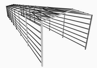
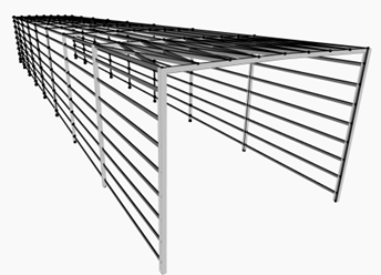
Case 1 Case 2
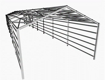
Case 3 Case 4
The data presented in the preceding table clearly indicates that the overall weight is more significantly influenced by the height of the structure than by the roof angle.
Limitations of the model
Higher roof slopes (more than 10 deg.) will require additional structural elements and may result in increased construction costs, and this is not considered in this model. So, although the 4th case has the least structural weight and cost, it is not realistic as it will need reinforcement such as additional bracing.[3][4]
For that, case 2 and 3 are better cases to choose from, and I think the optimum choice is case 2, considering this model.
References
[1] Noemi Subelza. Displacements of Side Walls with Wall-Girts in Industrial Buildings Under Vertical Settlements. 2021
[2] https://www.limtrade.de/metall
[3] National roofing contractors Association- NRCA
[4] Alan Scott Hoback, Naser Katanbafnezhad. Optimum roof angles of steel gable frames with pinned supports. 2020