Tram tracks are an important part of local public transport. Their expansion is intended to promote the transfer of the population from private motorized transport to public transport. This can reduce CO2 emissions and optimize the cityscape. In addition to the decision for one of the tram track types (road-bound, independent and special track), the adjustment of the geometric properties shall allow the fast generation of different design options and thus support the decision process. In the following, a tram track ontology is presented, which provides a knowledge base for communication and exchange. Above this, a parametric model developed with Dynamo is described.
Ontology Model
The .owl file for the ontology can be found here.

Image 1 Ontology Tram Track
A tram track infrastructure is a connection of NetElements and NetRelations. A NetElement is primarily a station, but it can also be other structural assets such as bridges or crosswalks. The NetRelation is composed of track relations, track elements and the axis, which defines the course of the tram track. A track element always occurs when the regular structure of the track is disturbed. This can occur at crossings with other tracks or when changing to other tracks via switches. The actual structural system of the tram track is described as the TrackRelation. This is composed of the superstructure and substructure. An important part of the substructure is also the embankment, which enables guidance through uneven terrain, stability and functional load transfer.
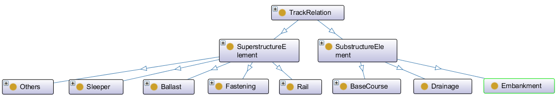
Image 2 Ontology Tram Track class Track Relation
Parametric Model
The .dyn file for the parametric model can be found here.
The focus for the development of a parametric model was on the superstructure. The parameters track gauge, sleeper length, sleeper spacing and bi-block sleeper distance can be used to change the geometric properties of the model. Furthermore, the decision can be made whether the track is a slab track and whether the space between the sleepers has been filled with ballast or concrete. To establish the logic of the model some relations and constraints must be respected. Here is a list of the most important ones:
- The 0-height is located between rail and sleeper.
- The rail is always on the sleeper.
- The height of the ballast or concrete corresponds to the height of the sleeper.
- If slap-track = true and material between sleeper = concrete : the concrete track gets the same height as that of the rail.
- If slap-track = false and material between sleeper = ballast : no concrete track is available
- If bi-block-sleeper = 0 : The sleeper is a monoblock sleeper, a connecting element is not necessary.
- If bi-block-sleeper > 0 : The sleeper is a bi-block-sleeper, a connecting element replaces the missing part of the sleeper.
- Ballast as material is only possible with a mono-block-sleeper.
- The center of the main axis is the center of the mono switch and the bi-block switch + connecting element.
- The gauge is smaller than the length of the sleeper.
Three different options were developed in the experimentation phase. Variations were made between the geometric properties as well as the materials. The differences in terms of resulting weight and cost were determined. The creation of the models and determination of the performance criteria was very fast, which could have a great advantage for the design phase of tram tracks.It turned out that the comparison of the options in terms of their performance criteria was not sufficient to make a final evaluation

Image 3 Parametric Tram Track