A waste water plant deal with different kind of contaminated water, like surface water, rainwater and waste water (municipal, agricultural, and industrial waste waters). It is made for securing and maintaining an adequate water quality for the effluent distribution system, which are usually natural waters like rivers. The treatment of waste water is one of the essential factors in the development of human settlements. The treatment of water has a rich history of practice and scientific developments. Nowadays the design of waste water plants got more sensitive and challenging, due to water quality regulations and analytical capabilities for detecting contaminants. The treatment of water encompasses multifaceted models of waste water plants and its variations in general, the transformation of contaminated waste water into treated effluent can include physical, chemical and biological processes [1].
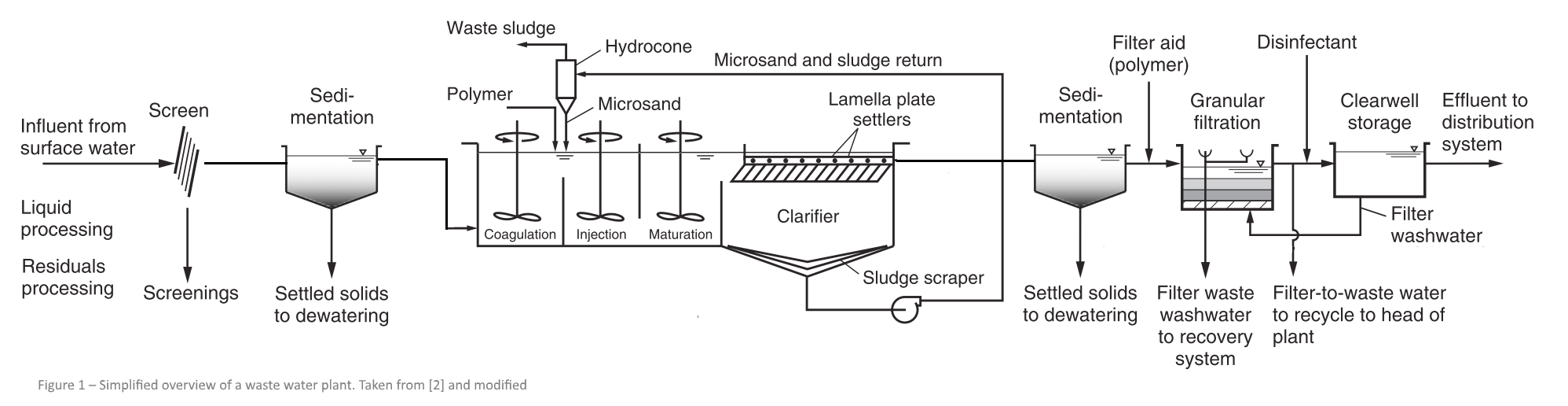
Figure 1 shows a short overview of a model from a specific waste water plant. It provides some common processes and components for the treatment of municipal waste waters.
Waste water plant – components and processes
The input parameter for the treatment is the flow of water with specific parameters, like the volume and loads including minimum and maximum values. In the primary step a screen separates large objects like plastic and rags to protect subsequent equipment (e.g. pumps or filters). The screen is usually a upstream equipment for the following sand trap. The sand trap is a kind of sedimentation basin, where heavy solids settle to the bottom, while oil, grease and lighter solids float to the surface. The corresponding process in a sand trap is sedimentation [2]. The next step is commonly the activated sludge process. In two steps dissolved and suspended biological matter will be removed. In a flocculation basin air is been injected into the constantly mixed water. Thereby suspended solids aggregate forming flakes that can be collected and separated through sedimentation or filtration. To support the flocculation clarifying agents can be used, because they are destabilizing the electrostatic charge whereby finer particles collide and agglomerate under the influence of Van der Waals’s force. Common clarifying agents are cations such as aluminium chloride, aluminium sulfate, iron chloride and iron sulfate. The next step of the activated sludge process occurs in the clarifier, which comprised a media (e.g. lamella plates) whereon indigenous micro-organisms borne and grow. These micro-organisms reduce the organic content of the water while producing biological mass which discharges on the bottom of the basin. The settled material (sludge) is separated, one fraction is returned to the head of the flocculation basin, in order to re-seed the new entering waste water. The remaining part of the sludge is collected and treated in further steps (e.g. through digestion) [3]. Another sedimentation basin is following the active sludge process. As well as in the sand trap, heavier parts being settled and separated. To allow rejection of the water into a sensitive ecosystem a granular filter is used. Filtration removes finest suspended solids and bacterial flocs [2].
Ontology
The ontology represents an appropriate transfer of the waste water plant with the required main functions and components into a logical model. Therefore, it is necessary to come to a compromise for the decomposition of the system – physical, functional and logical. The logical model concentrate on the interdependency of components and processes of a waste water plant. The main engineering challenge for a waste water plant is to combine components and processes, thus they presuppose each other for the dimensioning of a waste water plant.
The ontology includes, a hierarchically arrangement and properties that will describe components and processes of a waste water plant by providing the required information. Moreover, it is significant to provide information regarding the relationship between different components and processes.
To develop the logical model for waste water plant and its decomposition, the suggestions of Noy and McGuinness [4] were followed. Those suggestions were followed to define different classes and a class hierarchy to comprise such class system that follows the “kind-of” relation. Thereby every subclass represents a concept that is “kind of” the concept the superclass represents. The class hierarchy is developed with Protégé and shown in figure 2.
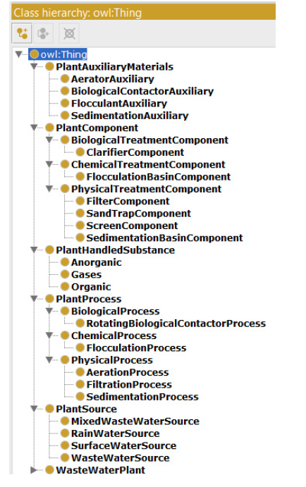
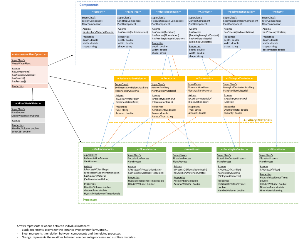
Figure 3 illustrates an overview of the class system, the created individual instances and the relation between them. The boxes show the individual instance of a class, in blue for the plants components, in green the plants processes and in orange the plants auxiliary materials. The first line state the individual name of the instance. The second line refers to the superclasses of the instance. The third line shows the used axioms for this instance. The last line provides information about the property, on the one hand the kind of information and the corresponding datatype. The arrows showing relations (black: hasProcess, orange: hasAuxiliaryMaterial).
Parametric Model
The first step was to find an appropriate design challenge. The parametric model just focuses on one component of the waste water plant – the sand trap. The sand trap is usually the second step after a screen in a waste water plant, where heavy solids settle to the bottom, while oil, grease and lighter solids float to the surface. The collected substances will be removed. The corresponding process in a sand trap is sedimentation. The dimensioning engineer of a sand trap must overcome some challenges, because the incoming water can show diversified variations of volume, flow velocity and load. In consequence, a welldesigned sand trap should be working toward the incoming volume flow peaks and balance the necessaire sedimentation rate (by taking the grain size and density of the material in account) with the residence time in the sand trap. Usually the incoming volume flow of waste water cannot be influenced readily, sometimes relief structures are being built to handle high differences between the usual volume flow and high peaks. However, the design of the sand trap´s cross section and the length of it are the common parameters that will lead the design.
To find a preferable realistic way of designing, the standards dimensioning a sand trap was obtained from DIN 19551-3. Figure 4 shows possible design of a sand trap cross section. The “Deutsche Vereinigung für Wasserwirtschaft, Abwasser und Abfall” (DWA) refers to this standard and shows different ways to calculate the related parameters for different cases. [DWA KA-5 2008]. Following these recommendations, a model for a sand trap was designed.
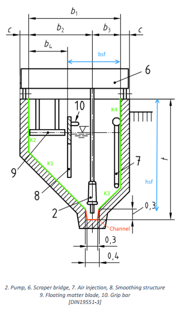
The calculation is based on the idea, that the sand trap must provide such cross section that allows the heavy solids to settle. It is calculated with division of volume flow by maximum velocity. The maximum velocity which is given by DWA is 0,2 m/s. The idea of the model is that the volume flow can be chosen freely, thereby a possible design for a sand trap could be modelled by a given volume flow. According to the calculated cross section and assumed parameters for the angle and bsf, the height of the sand trap can be calculated. The angle is given in range by DWA as well. bsf and hsf are calculated with the given volume flow and a ratio between bsf and hsf (bsf/hsf in beween 0,8 and 1,0) that have to be comply with. In the next step the length of the sand trap can be calculated, therefore the previously calculated cross section, the volume flow and the retention time have been considered. According to the DWA, the retention time is 300s. Now the single width (b1 – b4) can be calculated. At this point all essential parameters for designing the cross section are known.
With the calculated parameters and the theoretical background, it is possible to implement a design model. Blender and Sverchok are the softwares for implementation. Firstly, Sverchok Nodes are being used to introduce the input parameters and do the mathematical calculation for the related parameters. By that, it is possible to create a geometrical model. Accordingly, the idea is, to parametrise the green painted lines (K1-K4) in Figure 4. In threedimensional view, those lines are planes. To insert them in Blender, the Sverchok node “plane” is used. Each position in the room is modified by vector position, translation and rotation – Sverchok nodes: “Vector”, “Move”, “Rotation”. The intersections between the lines/planes are also parameterised. In Blender, the planes are represented by vertices, edges and faces. They are reproduced with the nodes “List Join”, “Viewer Draw” and “ViewerBMeshMK2”.
In conclusion, the idea is, that the parametric model provides a design suggestion for a given volume flow. It can also provide different geometrical variations for the same volume flow. In this case, the input parameters like bsf and alpha should be modified and the parametric model should give a new geometrical option for the same cross section.
Sewerage
Waste water treatment is one of the essential factors in the development of human settlements. Municipal buildings produce waste water, regardless of being part of a health resort in a small city or an inner city hospital in a metropolis. Waste water plants are made for securing and maintaining an adequate water quality for the effluent distribution systems, which are usually natural waters like rivers. In order to integrate the model of a waste water plant into the context of different settlements it is necessary to establish a connection between the plant and the waste water inducing buildings. Therefore a sewerage system transports the discharge to the plant.
References
[1] Fritsch, P. et. Al.: Taschenbuch der Wasserversorgung. 15. Auflage. Vieweg+ Teubner Verlag. 2010
[2] Crittenden, J. et. Al.: MWH’s Water Treatment – Principles and design. Third edition. John Wiley & Sons, Inc. 2012
[3] Braha, A.; Groza, G.: Moderne Abwassertechnik. John Wiley & Sons, Inc. 2006
[4] Noy, N.; McGuinness, D.: Ontology Development 101: A Guide to Creating Your First Ontology. Stanford University