Weakness Of Concrete Dams:
Unless reinforced with embedded steel bars, concrete is weak in tensile strength; that is, it can easily crack or be pulled apart. Concrete dams are therefore designed to place minimum tensile stress on the dam and instead to take advantage of concrete’s great compressive strength. The chief constituent of concrete, cement, shrinks as it hardens, and it also releases heat as part of the chemical reactions that occur within the cement during the process of hydration (or hardening). Because of the massive quantities of concrete used in a large dam, shrinkage caused by cooling can present a serious cracking hazard.
Various expedients are used to counter the likelihood of cracking, and much attention is often paid to reducing the amount of heat generated by the concrete. Concrete is usually cast (or poured) in separate, distinct blocks with heights (or “lifts”) of no more than about 1.5 metres (5 feet). Gaps between these blocks may be left to facilitate heat dispersal, and these gaps can be filled in later with cement grout. Low-heat cements may also be used, and these are specially blended so that the production of heat by the setting concrete is minimized. In the interior portions of a massive concrete dam, where impermeability or strength in resisting climatic and chemical deterioration are not particularly important attributes, the amount of cement in the concrete mix can be reduced; in turn, this reduces the heat generated. The cement content, and therefore the heat caused by hydrating, can also be reduced by using aggregate consisting of large stones. It is also possible to use fine-grained materials, such as fly ash (pulverized fuel), as filler, reducing the total cement volume in the concrete. Another technique is to use air-entraining agents that permit using a lower water-to-cement ratio in mixing the concrete. Techniques used to speed the cooling process include replacing some of the water in the mix by ice, circulating cool water through pipes placed within the concrete (this technology was used to great advantage during the construction of Hoover Dam), and extracting excess water from surfaces by vacuuming.
High Performance Criteria:
Failure of gravity dam occurs due to overturning, sliding, tension and compression. A gravity dam is designed in such a way that it resists all external forces acting on the dam like water pressure, wind pressure, wave pressure, ice pressure, uplift pressure by its own self-weight. Gravity dams are constructed from masonry or concrete. However, concrete gravity dams are preferred these days and mostly constructed. The advantage of gravity dam is that its structure is most durable and solid and requires very less maintenance.
The horizontal forces such as water pressure, wave pressure, silt pressure which act against the gravity dam causes overturning moments. To resist this, resisting moments are generated by the self-weight of the dam. If the resultant of all the forces acting on a dam at any of its sections, passes through toe, the dam will rotate and overturn about the toe. This is called overturning failure of gravity dam. But, practically, such a condition does not arise and dam will fail much earlier by compression. The ratio of the resisting moments about toe to the overturning moments about toe is called the factor of safety against overturning.
When the net horizontal forces acting on gravity dam at the base exceeds the frictional resistance (produced between body of the dam and foundation), The failure occurs is known as sliding failure of gravity dam. In low dams, the safety against sliding should be checked only for friction, but in high dams, for economical precise design, the shear strength of the joint is also considered. Factor of safety against sliding can be given based on
- Frictional resistance
- Frictional resistance and shear strength of the dam
To resist any type of failure concerning the strength of the dam is countered by the self-weight and reaction force of the retaining wall of concrete dam (Strength). Such capabilities are determined based on the water height in the reservoir which are the main factors of concerning when designing any strategy against failures and we need to provide sufficient strength likewise.
Formula for Water Pressure:
Therefore, we try out the empirical formula for calculating the pressure of water in the reservoir and accordingly a possible estimate of dam wall strength can be achieved with applying a factor of safety, which is (F.O.S*density of water+silt content*gravity force*height of water level).
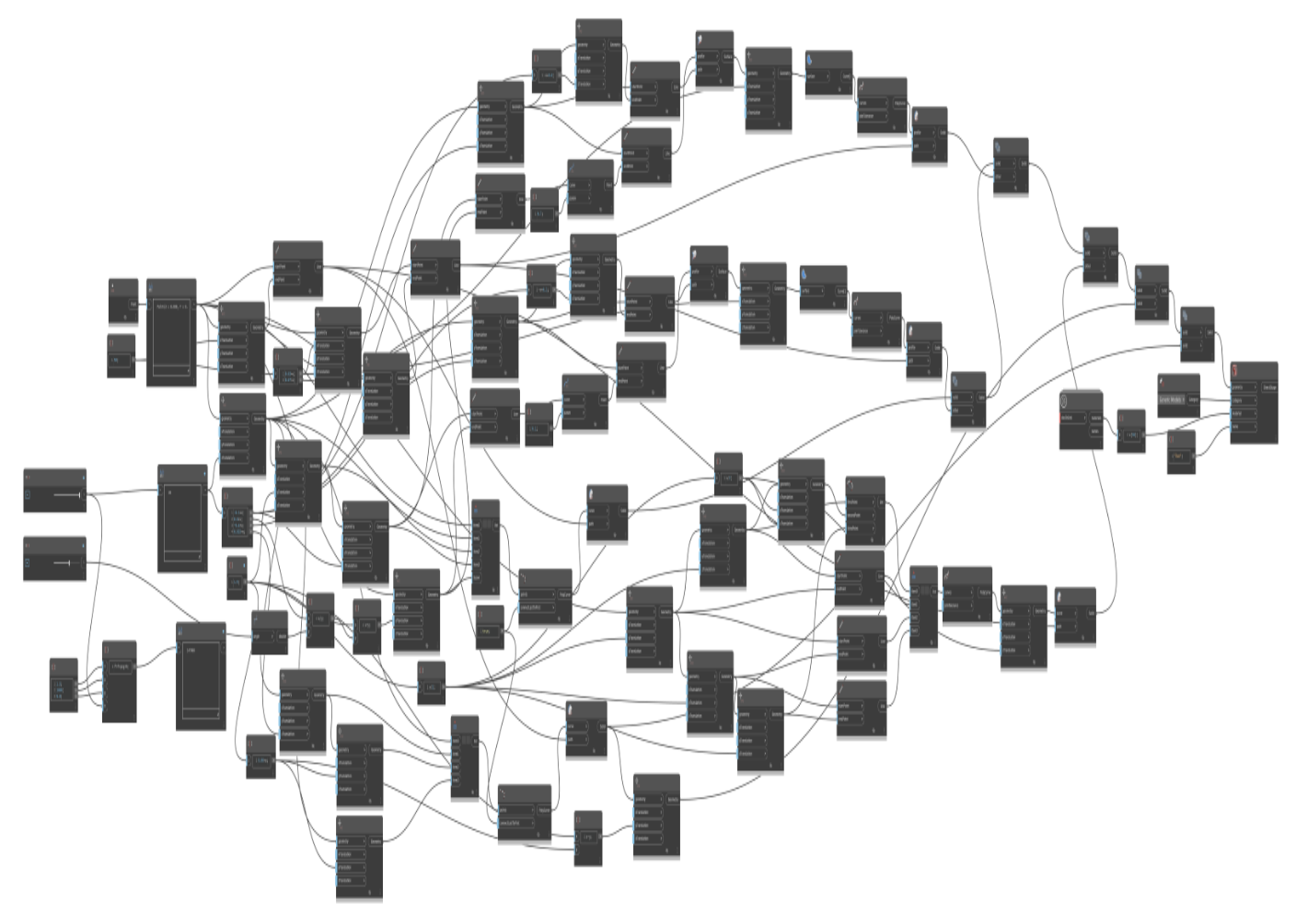
Parametric Design in Dynamo:
The following fig shows the parametric design of concrete gravity dam.
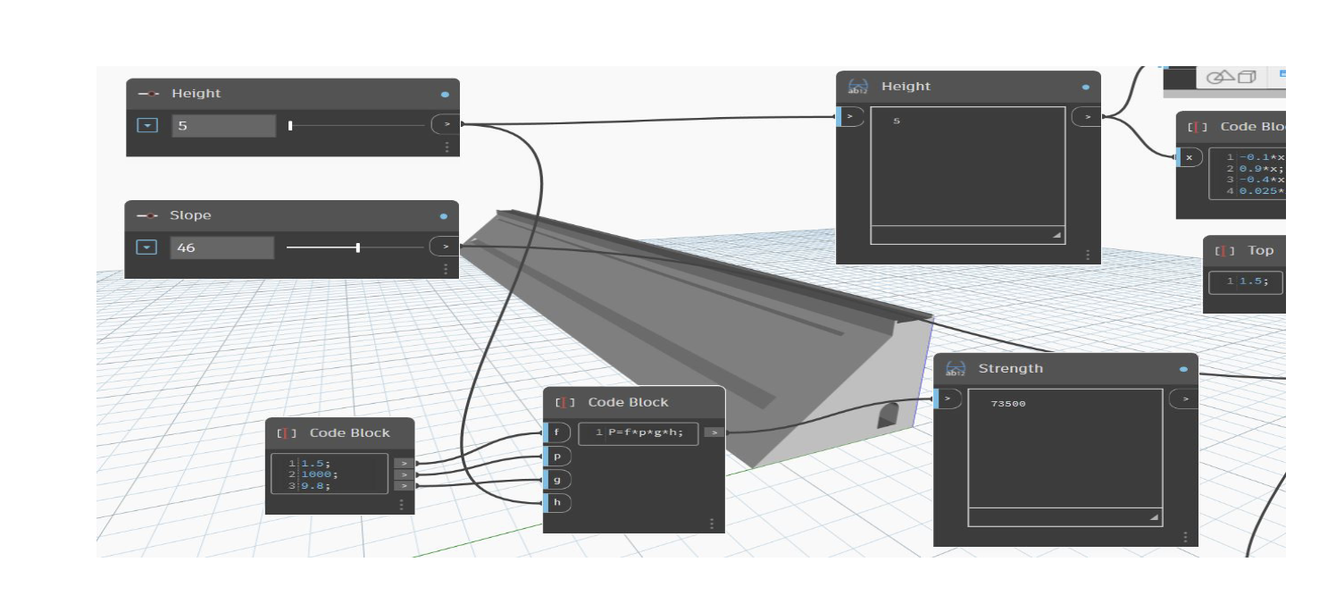
Scenarios:
In order to estimate the best possible design option for dam wall, three alternatives with small, medium and high levels of water are assumed for accurate and best design option.
Alternative 1.
In first alternative a design option is presented with strength against with very small height of water and corresponding strength is shown in fig.
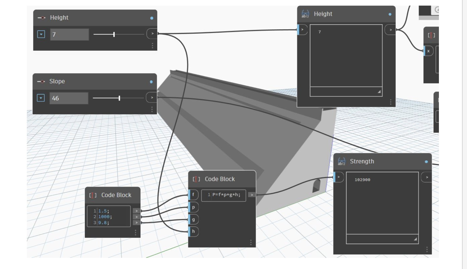
Alternative 2:
For this design option, a water level of 7 m is given while keeping upstream slope constant in first two options.
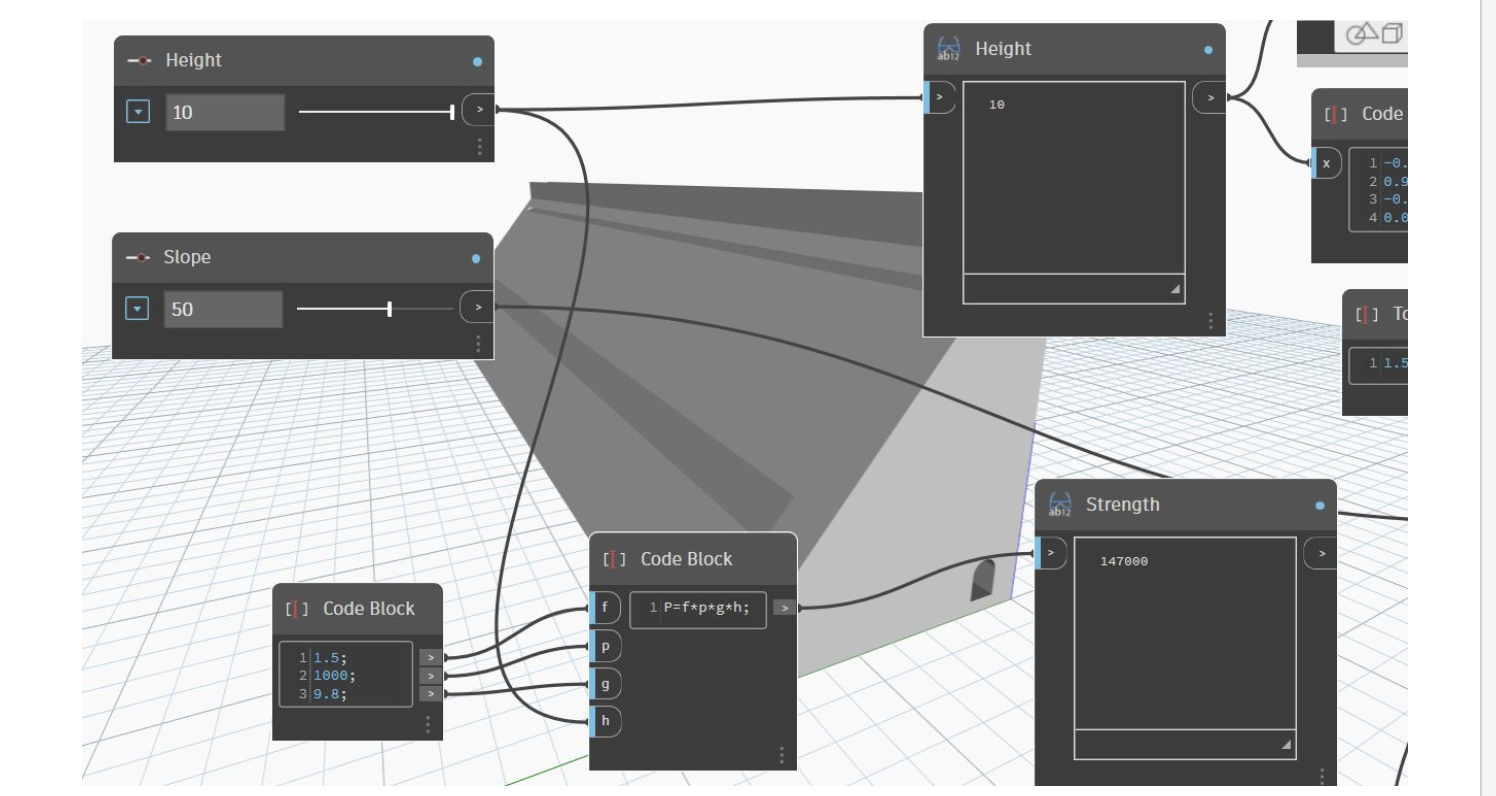
Alternative 3:
Here, highest degree of strength is achieved corresponding to the lateral forces, and it was notable that upstream slope also changed according to the strength as maximum seepage and drainage is expected in this case, and to counter this a gallery design option was also considered for this gravity concrete dam.
References:
http://www.diva-portal.org/smash/get/diva2:543834/FULLTEXT01.pdf probability of sliding failures for concrete gravity dam.
https://core.ac.uk/download/pdf/29154006.pdf (Concrete dams : theory and practice of construction)