The road in the Renewable Energy Park is an important interface between the existing engineering objects.
The curvy road itself consists out of three parts:
- Straight Part
- Curvy “S”-Road
- Curvy Road with Elevation
The Straight Part, especially, the length of the road can be randomly chosen and within easily combined with the length of other engineering objects.
The curvy road is illustrated in “S”-form (see 3D Model). Both types, the Curvy “S”- Road and the Curvy Road with Elevation uses the same algorithm (see figure 1).
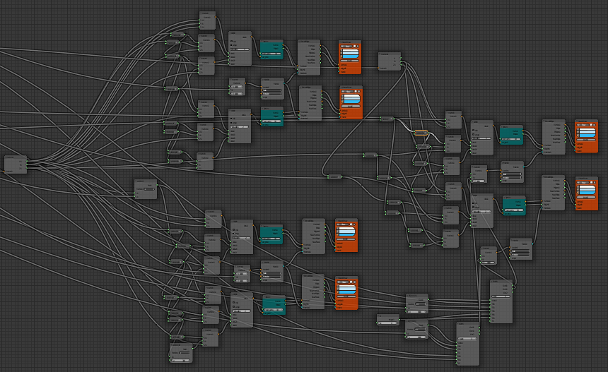
figure 1: Curvy Road Implementation
As you can see in figure 1, the curvy part is separated into two different parts.
The first part implements the “S”-road and includes the top and the bottom on the left side (see figure 1). In particular, the top part generates the left curve and the bottom part the right curve. Both parts combined arises the “S”. The second part, the implementation on the right sight (see figure 1), implements the curve with elevation.
The curve itself is generated though a “3pt Arc Node”. Within using this node, 3 points (x,y,z) get defined in an area and interlinked. The z-coordinate of the Curvy “S”- Road accesses on the z-coordinate of the Straight Road which ensures an even formation level. For the Curvy Road with Elevation the “3pt Arc Node” uses different coordinates. The x,y -coordinates of the Curvy Road with Elevation uses the same logic as the Curvy “S”- Road does only the z-coordinate defines the elevation.
An overview over the whole road implementation is seen in figure 2.
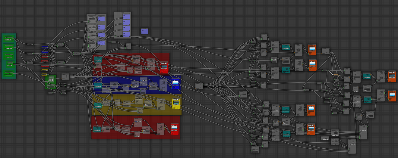
figure 2: Whole Road Implementation