Narrative
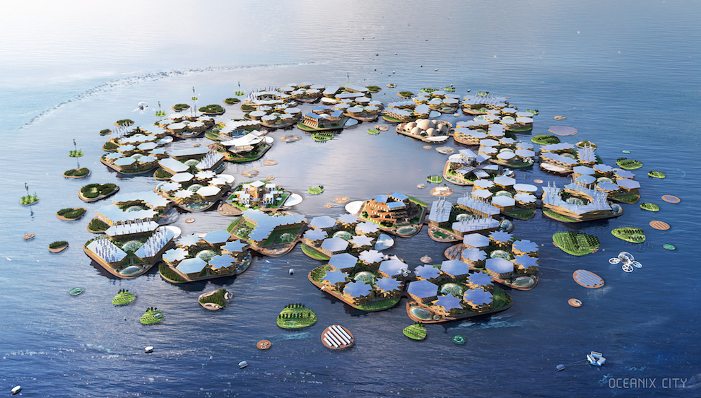
Figure 1 Rendering of UN-backed Oceanix Project off of Busan, South Korean
(Source: Global Construction Review)
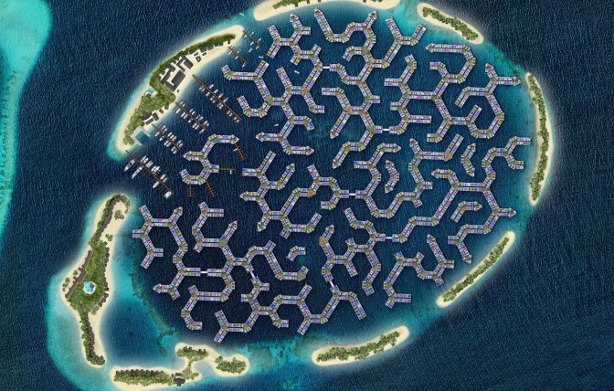
Figure 2 Maldives Floating City (MFC) presented by Dutch Docklands at World Economic Forum
(Source: World Economic Forum)
With rising sea levels and an increasing world populations, floating cities sound more like a viable design solution than a fantasy utopia. One example of where this project could take place is in the Maldives, an country consisting of clusters of several hundred small islands in the Indian Ocean. Because of the remoteness of this city, power could be supplied through integrated system that incorporates the following four sub-systems: (1) Off-shore Wind Turbines with a jacket and pile foundation and Floating Solar Photovoltaics anchored with (2) steel rope mooring lines to (3) treated wood Off-shore piles. Both of these energy sources connected to a (4) transmission tower which distributes power to individual housing units and sections of the floating city.
Background Research
Because of the unique nature of the integration environment and the limited existing research, extensive research is needed in the life cycle analysis and maintenance planning so stakeholders and designers have more information about the repair and maintenance strategy and the system design with new insights from the LCA and some multi-parameter optimization for minimizing costs, maintenance times and maximizing time in-between maintenance interventions. The foundation for the background research is the reports and background research from the individual subsystems and their individual life cycle assessments and maintenance strategies. Both the understandings of different design configurations for their emissions through the life cycle assessment and the frequency of their repairs and the duration of the repairs are combined and optimized in the integration.
Schematics
Developing this integration storyline also required developing context for interfaces and connections between the individual systems. In this sense, it also important to understand how the individual systems influence each other. The Floating Solar PV Park is grounded by steel rope mooring lines which are grounded to the treated wood pile foundations, therefor these two systems are directly connected to to each other. A failure in the pile foundation would lead to dangerous risks in the mooring line, but a failure in the mooring line does not raise much concern for the treated wood foundations. The Floating Solar PV Park also provides power directly to the transmission tower. The transmission tower is also situated on top of treated wood piles, and in similar fashion, a failure in the pile foundation is dangerous for the transmission tower. Because one renewable energy source alone is conventionally not seen as a sufficient and secure means to provide power, the off shore wind turbines are also providing power. However, the offshore wind turbines are set in the ground with a steel jacket and steel pile system that require a different maintenance strategy. One thing that the mooring lines, the off shore wind turbines and the treated wood pile foundations share in common is that repair and maintenance is performed underwater.
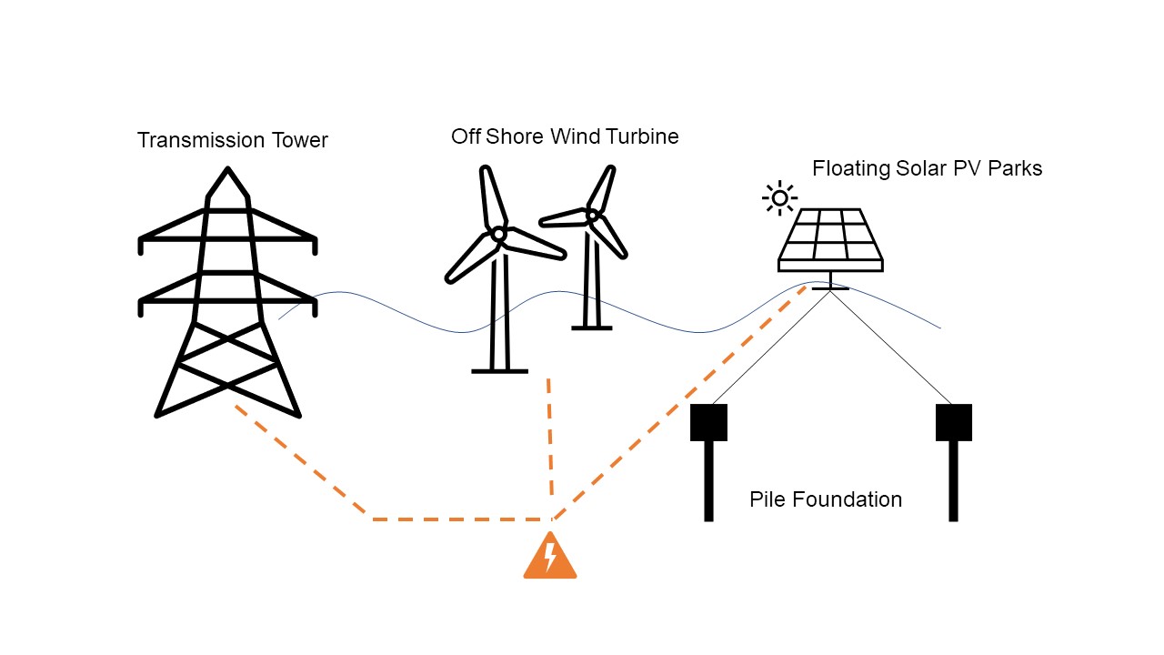
Figure 3 Schematics Layout
Integration Context of the civil systems