Olympic Park Civil System
Concept
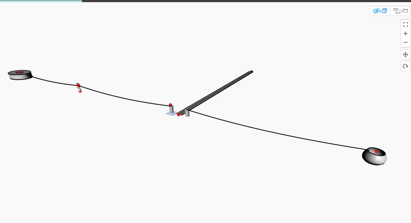
The core idea of the combined model is to create a system, in which swift connectivity among subsystems is ensured. This takes the form of building transportation routes among these subsystems that allow the accessibility for Olympic park visitors.
Connectivity
This is ensured, as mentioned in the integration context, by two ways of transportation:
– Bus line (from terminals to Cable Car stations).
– Cable Car (from Tower Stations to Leisure Park – Leisure Park to elliptical Stadium).
(from Tower Station – circular Stadium).
Purpose of parametric model – Evacuation Procedures
Traffic aspect
We set out a goal to be achieved through altering and redefining new parameters. This goal is to have a reliable evacuation plan for visitors in case of fire emergencies inside the stadium. The key parameter for this is the amount of visitors traveling from the stadium back to the airport runway. Therefore, the input parameter “Traffic Load” referring to the allowed amount of people on one Gondola has to be accordingly chosen with the results of the evacuation assessment. Upon calculating the amount of visitors inside the stadium based on its area, we compare the amount of people that need to be evacuated per Gondel to the allowed amount of people per Gondola, which gives us the Traffic Overload.
In the course of area calculation, the elliptical stadium had a bigger space, which makes it the critical stadium to be considered in the evacuation plan.
Following assumptions have been made:
– Service Load inside the stadium 5 kN/m² [1]
– 30% of the whole visitors inside stadium are located on the rooftop for evacuation
– Evacuation time frame 20 minutes [2]
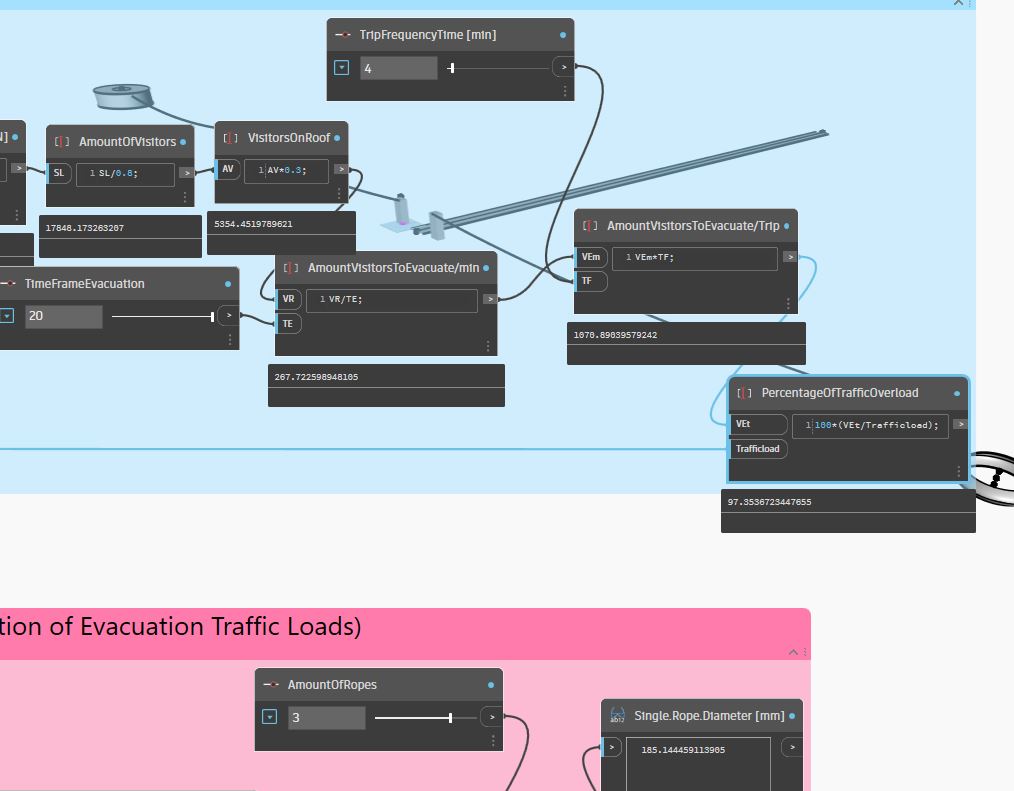
Fig 1 – Calculation nodes for evacuation assessment
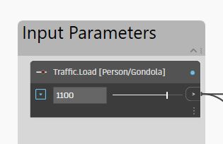
Fig 2 – Input parameter for allowed amount of people on two Gondola
Evacuation Plan factors:
– Trip frequency (1 trip every 4 min)
– Time frame evacuation (20 min)
– Allowed amount of People inside two Gondola (550 Visitor/Gondola)
As a result, we notice the needed amount of people for evacuation is 1070 visitors/min, which means 535 visitors/ Gondola. Thus we have a traffic overload percentage of 97%
Structural aspect
By changing the amount of allowed people inside the gondola, the structural analysis of the load bearing cable in the ultimate limit state changes. This change can be seen reflected through fig 1, where the needed diameter of the rope is now 185 mm for 3 roped cable car system.
Design alternatives:
Trip frequency
By changing the trio frequency from one trip every 4 min to one every 3 min, we achieve the illustrated results in fig 3.
We recognize the needed amount of people for evacuation is about 890 visitors/min, which means 445 visitors/ Gondola. Thus we have a traffic overload percentage of 73%
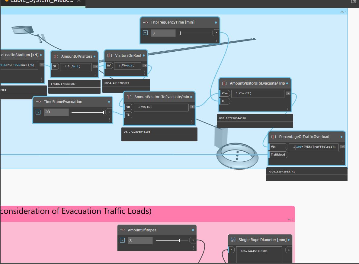
Fig 3: first alternative with higher frequency time
Allowed amount of people inside the Gondola
By changing the allowed amount of people inside one gondola from 550 to 900, which require a specialized gondola design that can take this huge traffic load.
The amount of evacuated people would not change since the trip frequency is kept the same. However, the percentage of traffic overlaod is down to 44%. This reflects negatively on the structural rope design, which mean that the cable diameter has to be 236 mm to carry such heavy load.
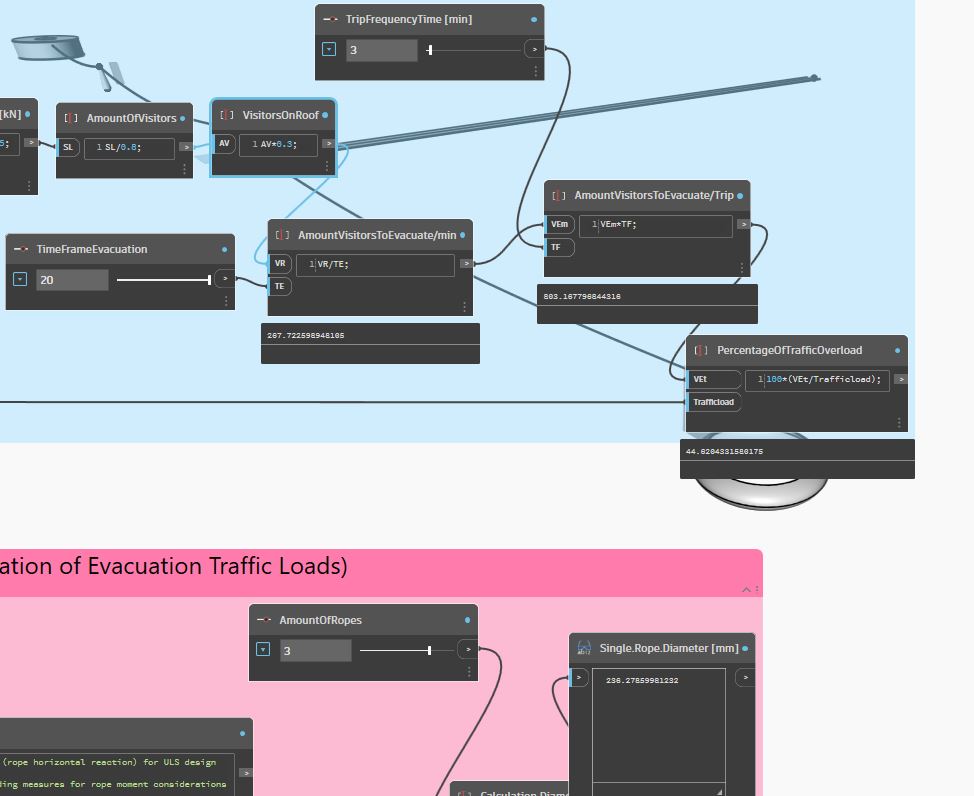
Fig 4: second alternative with higher amount of people per gondola
Height of the circular stadium
This alternative is examined in order to save the materials for the tower station connected to the circular stadium. By increasing the height of this stadium from 50 meter to match 75 meter (height of the airport station), structural aspect regarding the rope design would be easier since the two anchorage points of the rope are on the same height. However, this does not reflect on the transportation capacity, rather on the construction challenging of anchoring the rope in the circular stadium.
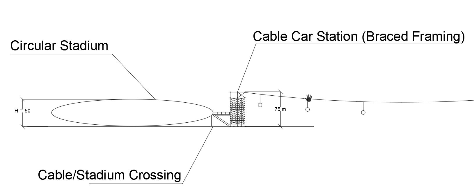
Fig 5 : connection point between circular stadium and tower station
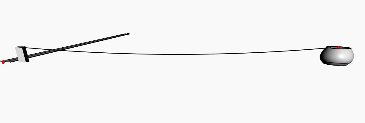
Fig 6: The different side view of higher curricular stadium without connection to tower station
References:
[1] DIN EN 1990 – Grundlagen der Tragwerksplanung
[2] https://www.firesafe.org.uk/fire-emergency-evacuation-plan-or-fire-procedure/