Introduction
This project illustrates the possibility to conduct a life cycle assessment of a RC Frame building.
The main material consumption in RC Frame Building is in the concrete beam-slab system[1]. Proper design of beam-slab system can reduce the floor height and reduce the overall height of the building, which is good for structural safety. Meanwhile, it can reduce the construction cost due to material saving. The Beam-Slab System of RC Frame Building is selected as the subsystem on which the Life-Cycle Analysis is conducted.
Goal and Scope Definition
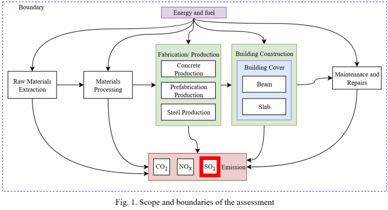
The main goal of this project is to do an SO₂ emission footprint analysis, and the scope and boundaries of this specific system are shown in Fig. 1.
Design Options
This project focus on the decisions that we need to take when we design the Beam-Slab system of the RC Frame Building. The design alternatives are presented and descriptions for these design options are in Tab. 1.
Option 1: Flat slab system
Option 2: Beam-Slab system
Option 3: Semi-precast Beam-Slab system
The materials used in this project for different elements under analysis is shown in Tab. 2.
Life Cycle Inventory:
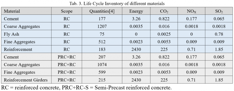
We present the composition of different materials used in each option. For each material, energy consumption (MJ/t), CO2, NOx, SO2 emission(kg/m3) during fabrication, processing, and construction are shown in Tab. 3.
The Quantities are the quantities of materials consumed to produce a cubic meter of concrete, respectively the reinforcement (in Kg) usually used for 1m3 of concrete. The quantities is calculated according to Soutsos et al.[4]
Life Cycle Timeline:
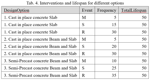
According to EN1990[5], the work life of normal buildings are defined as 50 years. Interventions and lifespan for different options are shown in Tab. 4.
- M = Maintenance: Routine inspections and minor repairs to maintain structural integrity.
- S = Component Strengthening
- R = Component Replace:
Life Cycle Analysis
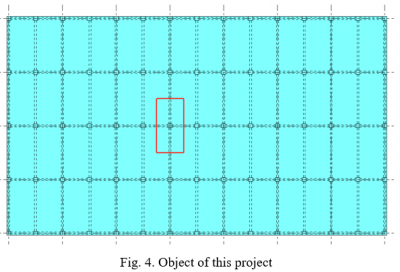
To simplify the calculation process, the object of study is the beam-slab system within the rectangle formed from the midpoint of one beam span to the midpoint of neighboring beam spans in x and y directions.
To consider the interventions in the total energy consumption and emissions, we define the number of interventions according to the intervention frequency. Then, to calculate the final total results, we set the intervention parameters to add the materials used for interventions to the total material consumption (Tab. 5).
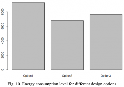
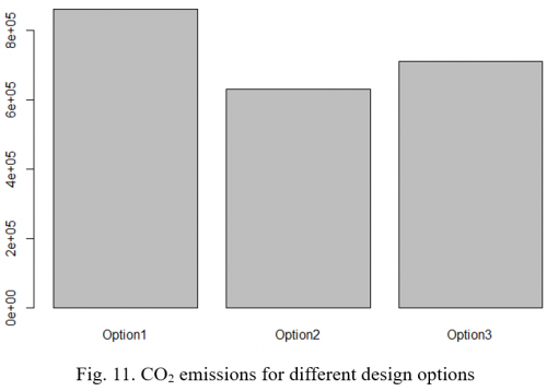
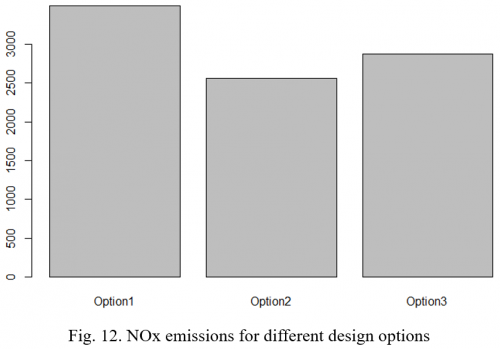
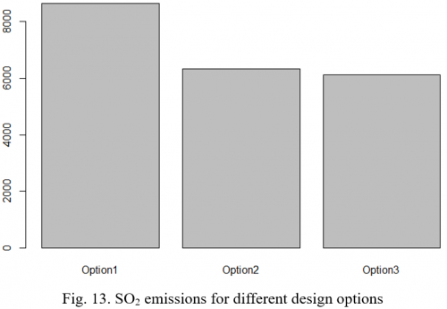
Then we calculate the life cycle energy consumption and GHG emissions within R. The results are shown in Fig.10-Fig.13
MCDM – Analytic hierarchy process (AHP)
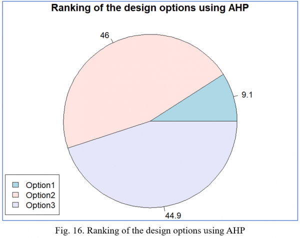
The result is calculated in R with AHP method and is visualized in pie chart (Fig. 16). It is obvious that the Option 1 (Flat slab system) is the worst choice, which is identical to our common concept. According to the result, Option 2 is a little better than Option 3.
Limitations
The slab we considered in this project is more like one-way slab, we should consider two-way slab later. In order to reduce carbon emissions, many countries have already made some policies to accelerate the development of precast concrete products. The policy factors are not considered in this project. The Consistency[7] of the AHP method used in this project need verification.
Results Analysis
Actually, precast concrete buildings can reduce the waste of construction materials since many components are prefabricated in the factory. And the shortage of labor market will seriously affect the traditional construction process. So many countries have already put prefabricated concrete buildings into practice.
But the relatively higher energy consumption and emissions must be taken into account. The joints of the precast concrete buildings should also be further investigated to ensure the strength, stiffness, and stability of the buildings.
References
- [1] Z. Yang and W.-Z. Lu, “A Two-Stage Genetic Algorithm for Beam–Slab Structure Optimization,” Buildings, vol. 14, no. 9, p. 2932, Sep. 2024, doi: 10.3390/buildings14092932.
- [2] Y. Ding and X. Ning, “Girder–Beam–Slab System,” in Reinforced Concrete: Basic Theory and Standards, Singapore: Springer Nature Singapore, 2023, pp. 403–445. doi: 10.1007/978-981-19-2920-5_11.
- [3] M. Hillebrand and J. Hegger, “Shear and interface shear of semi‐precast slabs with lattice girders under monotonic loading,” Structural Concrete, vol. 24, no. 2, pp. 3055–3076, Apr. 2023, doi: 10.1002/suco.202200423.
- [4] M. Soutsos, A. Hatzitheodorou, J. Kwasny, and F. Kanavaris, “Effect of in situ temperature on the early age strength development of concretes with supplementary cementitious materials,” Construction and Building Materials, vol. 103, pp. 105–116, Jan. 2016, doi: 10.1016/j.conbuildmat.2015.11.034.
- [5] H. Gulvanessian, “EN1990 Eurocode—Basis of structural design,” Proceedings of the Institution of Civil Engineers – Civil Engineering, vol. 144, no. 6, pp. 8–13, Nov. 2001, doi: 10.1680/cien.2001.144.6.8.
- [6] T. L. Saaty, The Analytic Hierarchy Process: Planning, Priority Setting, Resource Allocation. in Advanced book program. McGraw-Hill International Book Company, 1980.
- [7] A. Demir, A. E. Dinçer, C. Çiftçi, S. Gülçimen, N. Uzal, and K. Yılmaz, “Wind farm site selection using GIS-based multicriteria analysis with Life cycle assessment integration,” Earth Sci Inform, vol. 17, no. 2, pp. 1591–1608, Apr. 2024, doi: 10.1007/s12145-024-01227-4.
