Parametric definition of an Oscillating Water Column
Defining the design theme
OWC parametric models – argumentation on the selection of the parameters
The domain focuses on creating a parametric model of Oscillating Water Column. Main purpose to create the parametric model is to aid in structural design and analysis of it, thus making the marine engineers to alter the design with ease whenever it is required.
Design spaces and limits
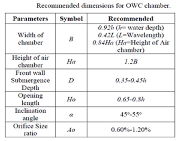
The main part of OWC is the air chamber which harness the most amount of air pressure to run the turbine, thus to generate electricity. Therefore designing this chamber is the most relevant need. The chamber has few parameters which need to addressed for increasing the efficiency level of OWC. Adhering to the standards by the parametric needs and designing the OWC with the parametric space & limit constraints is a crucial task while focusing on hydrodynamic efficiency of the system.
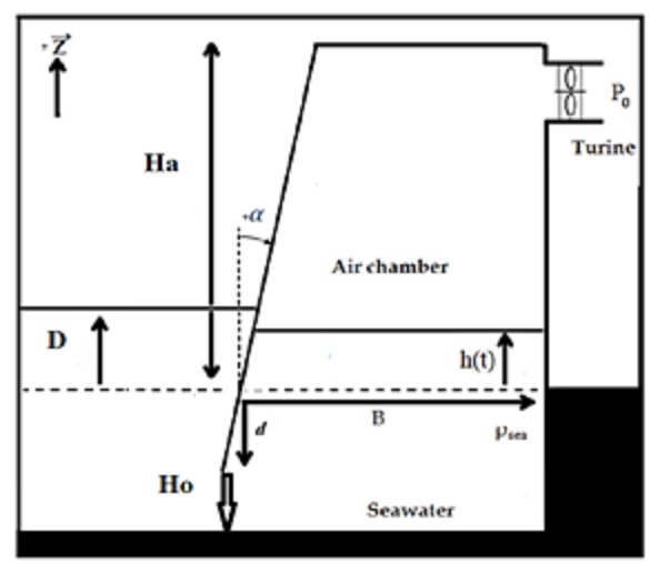
Oscillating Water Column Details
What’s the purpose of these parameters?
The air chamber dimensions of the OWC are the main parameter considered for structural analysis. This parameter influences most of the decisions taken during OWC design moreover decides the efficiency of the system. The length, width, height, inclination and air orifice of air chamber as a controlling parameter allows to use the parametric model on various onshore site conditions. After finding an appropriate place where tidal action is greater, the parametric dimensions can be decided based on the efficiency required. Major point to be highlighted is volume of the air chamber which allows the air column to get compressed above tides decides the amount of energy generated from it by rotating the turbine.
Definition of high-performance criteria
As an indicator of efficiency of OWC , these below mentioned high performance criteria parameters are taken into account.
Width of air chamber and inclination of air chamber wall has direct impact on pressure inside air chamber and natural frequency of the piston. Altering these two dimensional parameters , impact on high performance level indicators are carried out in this study.
|
Primary Objective |
Key indicator | Unit (SI) |
Extent |
|
Increased hydrodynamic performance of OWT |
Pressure inside air chamber | N/mm2 |
1000N/m2 |
|
Increase the natural frequency of OWC |
Natural Frequency ωn | Rad/sec |
0 – 3 rad/sec |
Design of Oscillating Water Column
Design Option 1
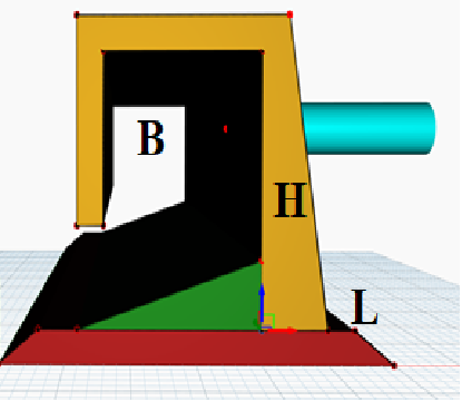
For initiating the design process, OWC dimensional parameters are identified for air chamber components including air orifice, break water and sloped floor. Standard values has been preferred from journals for the same. It is quiet essential for OWC to have breakwater to support the system as a whole, the dimensions adopted for the design of breakwater are 30m bottom width, 24m top width and slope of 1:2. The air wall chamber is designed after breakwater with necessary width, length and breadth, for the current design option 1 the wall chamber inclination is kept as zero as shown in the above figure ( L = 53m, W = 12m, H = 12m, ϴ = 0o). Small sloped surface floor is placed adjacent to the chamber to narrow the opening of wall chamber such that tidal waves gets into it through high pressure and compress the air taken inside. Orifice is created on chamber of radius 2m.
Considering design option 1, length , height of air chamber , air orifice radius and width of top and bottom portion of air chamber are decided for procuring the hydrodynamic efficiency indicator values. Therefore based on this, the pressure inside the chamber is computed for the same. Value obtained for Pressure inside the chamber is 146.949 N/m2. In order to study the effect of inclination of wall chamber, the ϴ is varied for three design options. For Design option 1, ϴ is taken as 0o, and thus the natural frequency of piston is computed by using the equation given for ωn, the value obtained here is 3.035 rad/sec, which is larger than the range given for it. Chamber width even have influence on wave frequency. The hydrodynamic efficiency increases with the chamber width at the low incident wave frequency vice versa at the high incident wave frequency. Also the peak efficiency of OWC occurs at a higher frequency and increases with decreasing the chamber width.
In the case of design option 1, area of cross section of chamber is considered to be in rectangular shape based on which volume of air chamber is computed. For other two cases cross section is considered as trapezoidal (design option 2) and triangular (design option 3), for volume computation. Air orifice radius is kept constant for all three design so that comparison can be done between these options.
Design Option 2
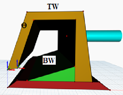
Design Option 3
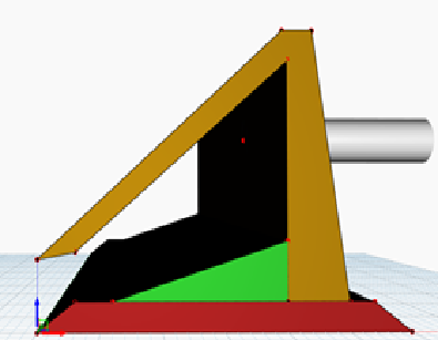
Similar like design option 1, length , height of air chamber and air orifice radius is kept constant and the width of top and bottom portion of air chamber is varied for obtaining pressure inside the chamber for ( L = 53m, top width = 12m, bottom width 17m, H = 12m, ϴ = 45o) design option 2 & ( L = 53m, W = 17m, H = 12m, ϴ = 56o) design option 3. Thus while computing the pressure, value obtained for Pressure inside the chamber is 177.65 N/m2 for design option 2 and 104.77 N/m2 for design option 3. In order to study the effect of inclination of wall chamber on natural frequency of piston, the ϴ is considered 45 degree for design option 2 and 56 degree for design option 3. The values obtained for the natural frequency are 0.00148 rad/sec (design option 2) and 0.00126 rad/sec (design option 3). The three-option analysis shows that there is marked reduction in natural frequency of piston from design option 1 onwards due to the change in the inclination of wall chamber. Where as based on the volume of air chamber, the air pressure varies inside.
Conclusion
The best design option is design option 2,where the value of pressure generated inside the air chamber is higher when compared with other two options, more over it creates a natural frequency for piston which is in the prescribed range as stated earlier while defining the high performance criteria ( 0.001 – 3 rad/sec ). Thus the study readily shows how the change in chamber width would influence the pressure inside the chamber as well as how the inclination of wall of chamber effects the natural frequency of system. An optimized solution would be considering the inclined sidewalls and increased chamber width during the design stage which would aid flexibility and better hydrodynamic efficiency for the system.
Download Files
OWC parametric models