Engineering Challenge – Performance Goals
The ultimate goal of the parametric modelling is the sizing and design of the integrated system and optimization of the design inputs while consideration of how the individual systems interact with each other. This is all a means to creating an appropriate energy yield from the energy sources. In order to complete the integration context, a substation was added and in the background research and ontology, it was revealed that the design implications for the substation depend on the power and reliability of the energy sources. The amount of power the solar panels can provide is directly related to geometric design constraints for width, length and tilt angle. For the wind turbine, designers can change the rotary diameter of the blades to produce more power, but this lead to a large tower with a leger tower diameter. A large tower may also have the protentional to be situated in deeper water, perhaps effecting the designers choice for the thickness of the dam.
Development of Parametric Model
The most pragmatic way to create a parametric model ended up know being the integration of the individual dynamo models with the Speckle plugin, which upon attempting proved to return a lot of years. Instead a model was developed for showing the dam sized to the min/max specifications required for the integration context to hold the water upstream to circa 40 meters for the wind turbine and downstream to circa 20 meters. Furthermore, the individual model for a off shore wind turbine is integrated, that allows for designers to change the cross section of the column and in returns allows for the mounting of blades with a bigger rotor diameter and therefore also a bigger power yield. This is a balance act between the energy provided by the wind turbine and the solar photovoltaic panels downstream to provide appropriate power for the substation. The substation was not a research item of the active group members, so it is shown in a very abstract fashion in the model. In reality the substation would be sized last after extensive modelling and optimization of the design of the wind turbine and solar pv panels is performed. It should be noted that if the size of the the wind turbine is increased dramatically, it can no longer be recommended to house it in a depth of 40 meters and the dam should be resized and strengthened accordingly.
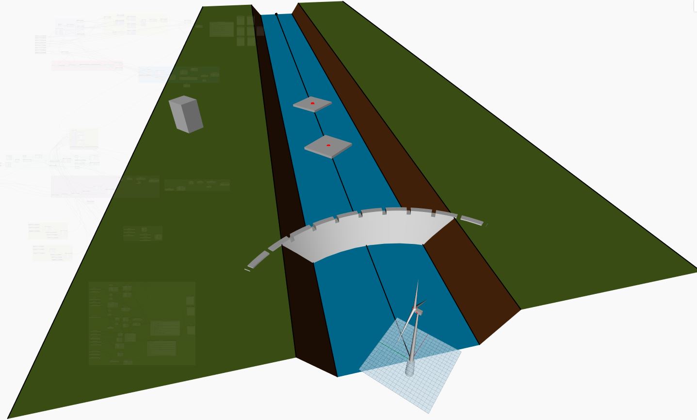
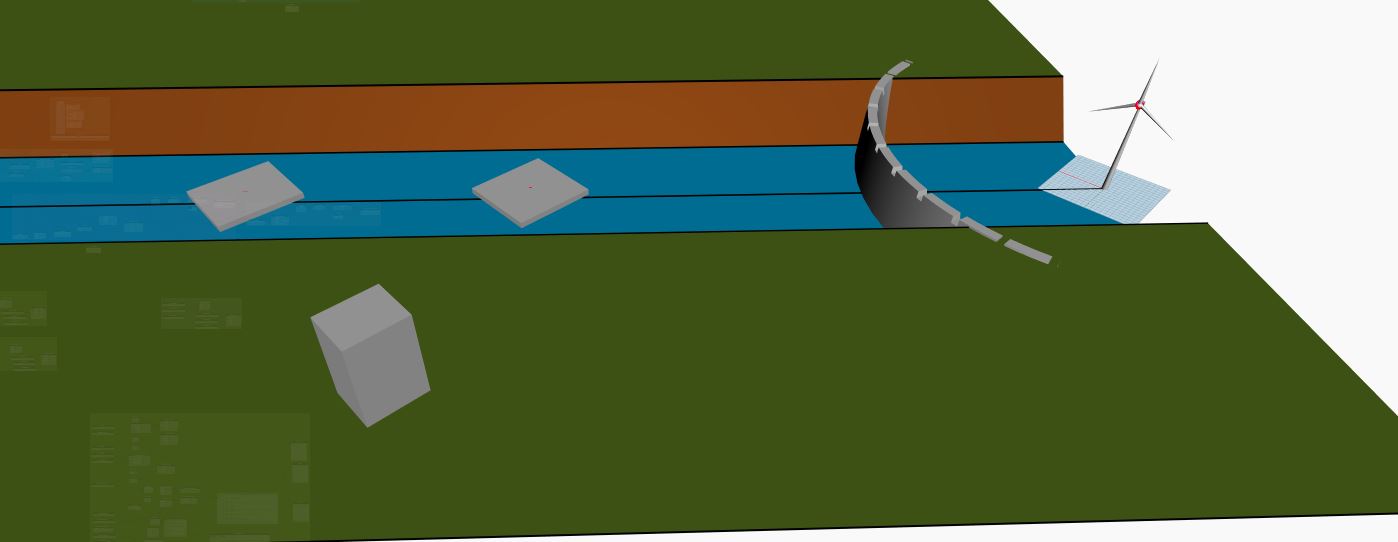
Figure: Integrated model of Dam, Solar PV, Offshore wind turbine and Substation.
Discussion
Most design codes would suggest that the concrete dam in the 50-75 meter range would need slab thickness to be 5-15 meters thick (see reference) depending on the sizing of the reservoir and maybe some considerations for local earthquake design codes, so unfortunately this leaves little freedom left for designers because the integration scenario is not very flexible about the required depths of 20 meter and 40 meter. For the solar photovoltaics, changing the tilt angle does not effect the wind turbine, but an optimal angle of about 40 degrees would improve the efficiency of the panels.
The sizing of width and length of the solar photovoltaic farm leads directly to the output potential, and that is also true for the rotary angle of the wind turbine. Because the optimization of this problem helps directly to meet the demand of the substation, the parametric modelling is it a great approach to review different design scenarios. What is however missing from the model is extensive research beyond the scope of this project for weather conditions, variations in the power demand, wind protentional, solar potential and perhaps the upfront costs of both the solar panels and the wind turbines.
Parametric Experimentation
In order to perform some design scenarios with the parametric modelling some assumed rated power outputs were taken from reference material found at the bottom of this page. Based on this information, and the assumption that 1 square meter of solar pv farm produces approximately 1000 Watts also take from reference material. Some design scenarios can be drawn up with the parametric modelling.
Design Scenario 1: 40 m rotary diameter wind turbine estimated to produce circa 500 kW,
+500 square meters of solar PV needed to meet powered to mee 1000 kW.
Design Scenario 2: 50 m rotary diameter wind turbine estimated to produce circa 700 kW
+300 square meters of solar PV needed to meet power demand assumed at 1000 kW.
Design Scenario 3: 60 m rotary diameter wind turbine estimated to produce circa 800 kW
+200 square meters of solar PV needed to meet power demand assumed at 1000 kW.
Design Scenario 4: 20 m rotary diameter wind turbine estimated to produce circa 1000 kW
no solar PV needed to meet power demand assumed at 1000 kW.
Design Scenario 5: 30 m rotary diameter wind turbine estimated to produce circa 250 kW
+750 square meters of solar PV needed to meet power demand assumed at 1000 kW.
It was also very helpful to view this different design scenarios in the dynamo model, because you may notice for creating the larger surface areas for the solar photovoltaic width and length combination should be selected in a manner that are practical and easy for engineer to install a maintenance.
References
Henderson, Andrew & Morgan, Colin & John, Bernie & Sorensen, Hans & Barthelmie, R. & Boesmans, Bart. (2002). Offshore windpower: A major new source of energy for Europe. International Journal of Environment and Sustainable Development. 1. 10.1504/IJESD.2002.002356.
Tasie, Nicholas & Sigalo, Friday & Alabraba, Matthew. (2018). Characterizing the Photovoltaic Solar Panel for Maximum Power Output. The Journal of Scientific and Engineering Research. 5.