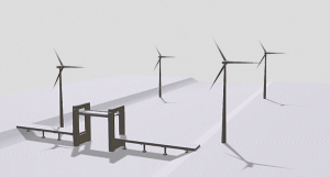
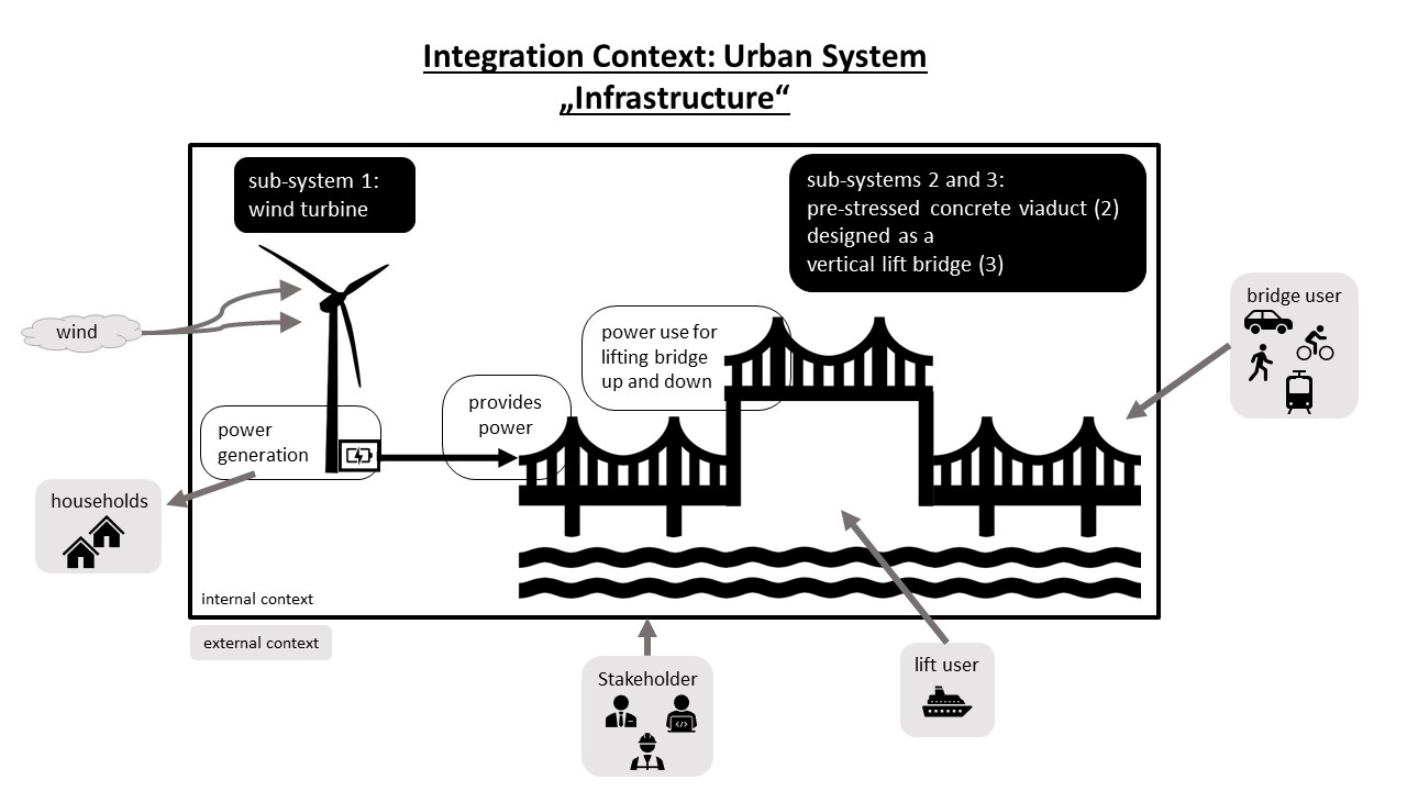
The integration context of our three individual sub-systems is shown in the figure below.
We have created an internal and external context.
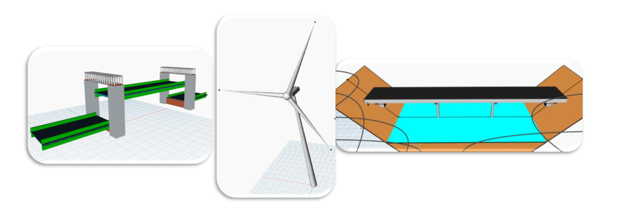
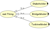
The internal context concerns the sub-systems and their relations. Together, they represent the holistically integrated system. The wind turbine generates power which is used by the bridge for lifting the deck up and down. The bridge itself is made of pre-stressed concrete and has the ability to lift a part of the deck. This means that by creating the urban system “Infastructure” we have reduced the number of individual systems frome three to two beacuse the bridge is unifiying the two individual systems vertical lift bridge and pre-stressed concrete viaduct .
The external context concerns other relations and dependencies for the individual systems. The wind turbine needs wind to generate power and can also provide households with power which is not used by the bridge. The bridge has different kind of users: the bridge user (car, train, pedestrian and bicycle) and the lift user (ships). We also have a group of stakeholder (e.g. designer, (sub-) contractor and vendor) which apply to all the sub-systems.
The main integration challenges we faced are to integrate the two bridge systems – vertical lift bridge and pre-stressed concrete viaduct – in a sensible way and to generate a connection of the wind turbine to the bridge system. The bridge challange was managed by including a lift part in the viaduct. In terms of ontology we had to remove entries which double. The connection of the wind turbine to the bridge was managed by calculating the power use of the birdge and the therefore necessary power generation by the wind turbine.
On the following pages we will show and explain our solutions for the integrated ontology as well as the integrated parametric model.
go to