Home / Group 3 / Integrated Civil System / Combined Parametric Model / Integration Challenges
Well defined Integration Challenges and Information supporting Integration
Inorder to integrate our system we tried two different scenarios where utility tunnel serves two different functionality.
Why choose functionality aspect scenario of tunnel ?
Our complete system is renewable energy park which needs to convey electrical connectivity to different residential, industrial and irrigation sectors. so this component links all the other three systems of renewable energy park. Through the aid of tunnel we can provide electrical services to all amphibious houses and other infrastrcutures.
Scenario 1
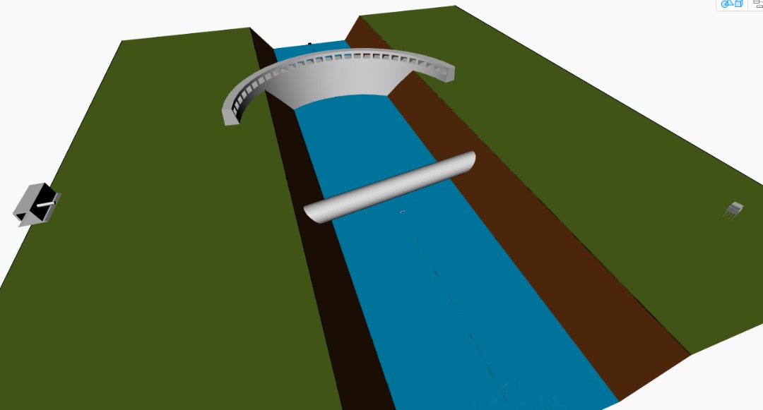
Utility tunnel is along the width of the river thereby joining two banks. Here it serves the purpose of laying pipes systems, fibre optics etc across the banks and giving a connectivity to other side of the bank.
Scenario 2
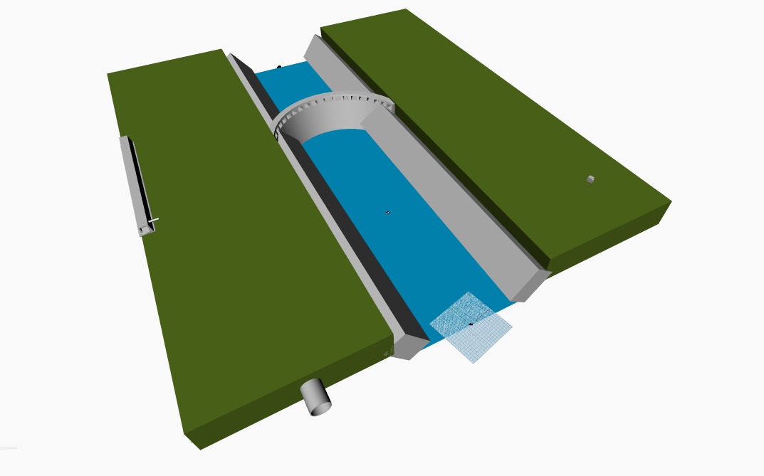
Utility tunnel is along the bank of the river being near to water column. Here it serves the purpose of carrying power supplies to the residential areas near to the left side of bank alone.
Out of the above two tunnel functionality scenarios we had put the design by high performance criteria option for scenario 1 alone as both scenarios have same behavioral mechanism .
Design behaviour and integration options based on High Performance Criteria.
As High performance criteria we have taken three parameters;
- River width
- Quantity of Concrete Material
- Flood Protection Strategies at various sites.
- River Width – HPC I
Dams are constructed in the upstream of river. Based upon the river width , naturally the design length to be considered for dam also changes. In this current study tunnel is connecting two banks , therefore when river width increases at different sites, the tunnel length automatically has to increase so as to connect the banks. OWC is a marine structure which ought to be at greater demarcated distance from dam area similarly houses should be built at around 20km away from dam sites in upper stream. Therefore the positioning of OWC and houses should be based on the setback distances allotted to them. Even while width of river changes from place to place , positioning of OWC and amphibious house system should rely on the set back distance.
Motive behind taking river width as HPC I
- When designing a renewable energy park comprising OWC , Tunnel, Dam and Amphibious house , IF the tunnel is crossing along the river then , naturally at different river sites tunnel length need to varied to link the banks as well as Dams constructed on rivers also vary in length based on different river stream sites. For other two systems OWC and Amphibious houses they have to be a distance further away from dam site as it should not have flood impact. So when river width is altered in dynamo file for various river sites , then naturally dam length, tunnel length , clearance distance of OWC and amphibious house also changes accordingly.
- Quantity of Concrete Material – HPC II
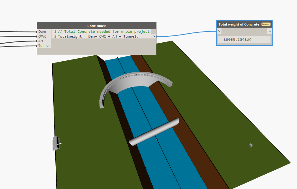
All the Renewable energy park systems are made of concrete , so the complete system is integrated based on the fact that the common material used in the construction of each of the system are the same. Therefore calculation of quantity of concrete required for the construction of each system can be calculated from the single dynamo file even if the design parameters are changed. This study enable to fetch the total quantity of concrete material required for construction of renewable energy park comprising systems like OWC, Dam, Tunnel and Amphibious House.
Motive behind taking concrete material as HPC II
- For different river sites, naturally the dam structure parameter, parameter of tunnel shall vary. Similarly based on number of people inhabiting in the area and number of households electricity production from OWC and Dam also vary. Inorder to convey the electrical systems through all amphibious houses tunnel parameters also vary. Since all these systems are linked based on renewable energy context, for different sites the capacities of dams, OWC, tunnels and number households also vary. Therefore the total concrete requirement to construct all systems also can be varied about the parametric variation.
- Flood protection strategies at various sites – HPC III
Flood mitigation is a major concern in the real world. Due to the change in climatic conditions there are chances of frequent flood in different river streams. Therefore at places of high rise in water level then the structures should be constructed on elevated banks. Therefore while designing systems on near by water area, the water level of the streams and the bank elevation should be optimally designed such that structures remain less effected by flood effects. So if the terrain is not elevated considering the river water level , then before any structural system construction, it is required to elevate the bank level by aid of external gravel materials or soil material thus by increasing the bank level or elevation.
Motive behind taking concrete material as HPC III
- When designing any infrastructure near to sea or river bank it will be major concern to elevate the structure and also to check the elevation of ground level . Therefore in a single dynamo file for this current study of renewable energy park based on different water level at different sites , the elevation change of ground level can be carried out. So while designing river with 5m water level, 10 m of increased ground level can be chosen and the site can be elevated in such a way before construction of these systems.
Download Files
Design option 1 Dynamo Design option 2 Dynamo