Design challenge
A parametric model was developed using Dynamo BIM to explore different breakwater designs. The primary goal of this parametric model is to support structural analysis and decision-making during the design process, reducing wave overtopping to ensure vehicle safety along the crest and limiting the concrete volume required for the structure while maintaining structural integrity.
The model aims to balance two high performance criteria:
- Overtopping Reduction Factor: measures the relative reduction in mean wave overtopping discharge due to the crown wall. The overtopping discharge is calculated using the EurOtop manual [1].
- Concrete Volume: Reducing the environmental impact by minimizing the amount of concrete required for the main armour and parapet wall, while maintaining structural integrity. The concrete volume of the parapet wall was calculated using Dynamo and the volume of the main armour elements was estimated using The Manual Rock [2] which considers the placement pattern of the elements.
Parametric Model
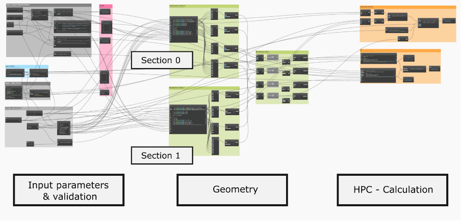
Using Dynamo BIM, a parametric model was developed to achieve the above objectives. As illustrated in Figure, this model is organized into three main areas, with distinct color codes representing their purpose and functionality.
- Input parameters and validation (left section): The left section of the model defines the input parameters and fixed values required for the calculations. The gray groups correspond to the geometry input of parapet wall and dike dimensions, and the main armour characteristics, while the light blue group contains the parameters related to wave height and period.
- Geometry (central section): The central section, highlighted in green, manages the geometric representation of the breakwater. Section 0 and section 1 were defined, both representing deep water areas; however, Section 1 corresponds to a position with greater depth. Points and polylines were used to establish the cross-sectional geometry, and solids were generated for the armour, crown wall, and core.
- High-Performance Criteria calculations (right section): The right section, highlighted in orange, calculates the high-performance criteria. These include: first, the overtopping reduction factor which indicates the reduction in average wave-overtopping discharge compared to a structure without a parapet wall, and second, the concrete volume, calculated for the armour using simplified formulas and for the crown wall using the geometric outputs from the central section.
Design alternatives
Through a series of experiments, the model demonstrated how variations in geometric parameters influence both wave overtopping and material efficiency. The key findings revealed that increasing the crest height effectively reduces overtopping but significantly increases concrete usage, while adjustments to parapet angles and bullnose geometry improve wave deflection without excessive material consumption.
Based on these insights, three optimized design alternatives were proposed:
Alternative 1: Prioritizing overtopping reduction.
In cases where minimizing overtopping is crucial, even in extreme weather conditions, a structure with a high hb ensures compliance. However, construction costs can be reduced by using steeper slopes (α). This alternative aligns with the structure used as a reference, the breakwater located at the submarine dock in Mar del Plata, Argentina, where the crown wall primarily serves to allow vehicle circulation.
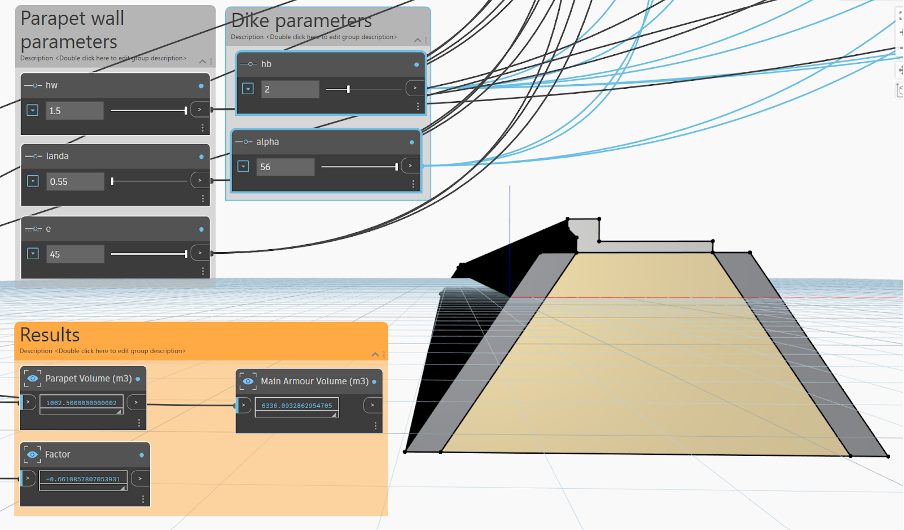
Figure 1: Example of geometry generated by the parametric model upon execution: Alternative 1
- Alternative 2: Ensuring high overtopping reduction with moderate concrete usage.
In cases where high overtopping reduction probability is desired while optimizing concrete usage, larger hw values combined with a parapet angle (ϵ) of approximately 30◦ are recommended. This design enhances wave deflection, reducing overtopping without significantly increasing the overall concrete volume. This approach is particularly important where the structure may be able to access under severe wave conditions.
- Alternative 3: Minimizing total concrete volume.
For scenarios prioritizing the reduction of total concrete usage, lower hw values paired with a bullnose angle (λ) of 30◦ are advised. This configuration improves wave reflection, effectively reducing overtopping. While not ideal for extreme weather conditions, it is well suited for structures where the access can be restricted when severe storms are forecast. One example can be the breakwater of IJmuiden, the Netherlands, where access during winter is limited.
All the parameters and the results are summarized in Table 1 and 3.
| Parameters | Alternative 1 | Alternative 2 | Alternative 3 |
| hw | 1.5 | 1.5 | 1.2 |
| λ | 0.55 | 0.6 | 0.6 |
| e | 45 | 30 | 30 |
| hb | 4 | 2 | 1.5 |
| α | 56 | 56 | 56 |
| Parapet Volume
(m3) |
Main Armour
Volume (m3) |
Reduction Factor
Q (%) |
|
| Alternative 1 | 1062.5 | 7468.4 | -31 |
| Alternative 2 | 1055.4 | 6336.1 -70 | -70 |
| Alternative 3 | 962.4 | 6052.8 | -80 |
References
[1] EurOtop. Manual on wave overtopping of sea defences and related structures: An overtopping manual largely based on European research, but for worldwide application. Second. Errata November 2019, 320 kB. Dec. 2018. url: https://www.overtopping-manual.com/assets/downloads/EurOtop_II_2018_Final_version.pdf.
[2] CIRIA, CUR, CETMEF. The Rock Manual: Chapter 5 – Hydraulic Design of Armour Layers and Filters. Jan. 2007. url: https://kennisbank-waterbouw.nl/DesignCodes/rockmanual/BWchapter%206.pdf.

