1. Introduction
A concrete slab as sub system for sump pit from previous assignment civil product will be considered and selected here in this project as a kind of barrier used to regulate water flow and store it behind that factory. Collecting water by using sump pit the Giga tesla factory berlin project from concrete structure factory where have been described in previous assignment is one the most efficient way to manage water resources which are used for ages. Hence, big sump pits are being an important subject and future distribution [1].
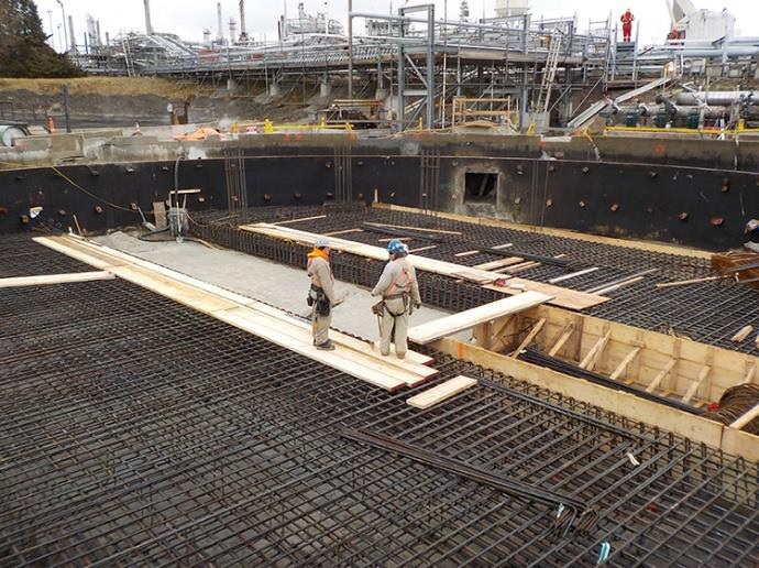
In many countries, many projects will be constructed sump pits in the future to respond to the increasing demand for clean energy and water resources. And to trap and filter water for pumping into a suitable discharge area. A perforated vertical standpipe is placed in the center of the pit to collect filtered water. The purpose of this practice is to remove excessive water in a manner that improves the quality of the water Environmental impacts of sump pits on air, land, and water are subjects of many past studies. Due to their ample use of cement, these projects have a significant environmental impact, including the production of carbon dioxide (C02), nitrogen oxide (N0X), carbon monoxide (C0), and particular matter (PM) [2].
Over the past decade, efforts have been made to evaluate the environmental loads of construction projects using the LCA method. LCA is an analytical methodology for evaluating the environmental impacts associated with a product system. With the growing interest in sustainable constructions, LCA has gained importance as an objective method to evaluate the environmental impact of construction practices.
LCA methodology has also been considered a useful and comprehensive tool in evaluating the environmental performance of concrete sump pits and factory constructions in big factories such Giga Tesla Berlin , and so was widely used in previous studies [3]. Several previous studies focused on the emissions from reservoirs, which are generated mainly in the operation and maintenance stages, which are thought to be the most important part of a concrete sump pits life cycle [4].
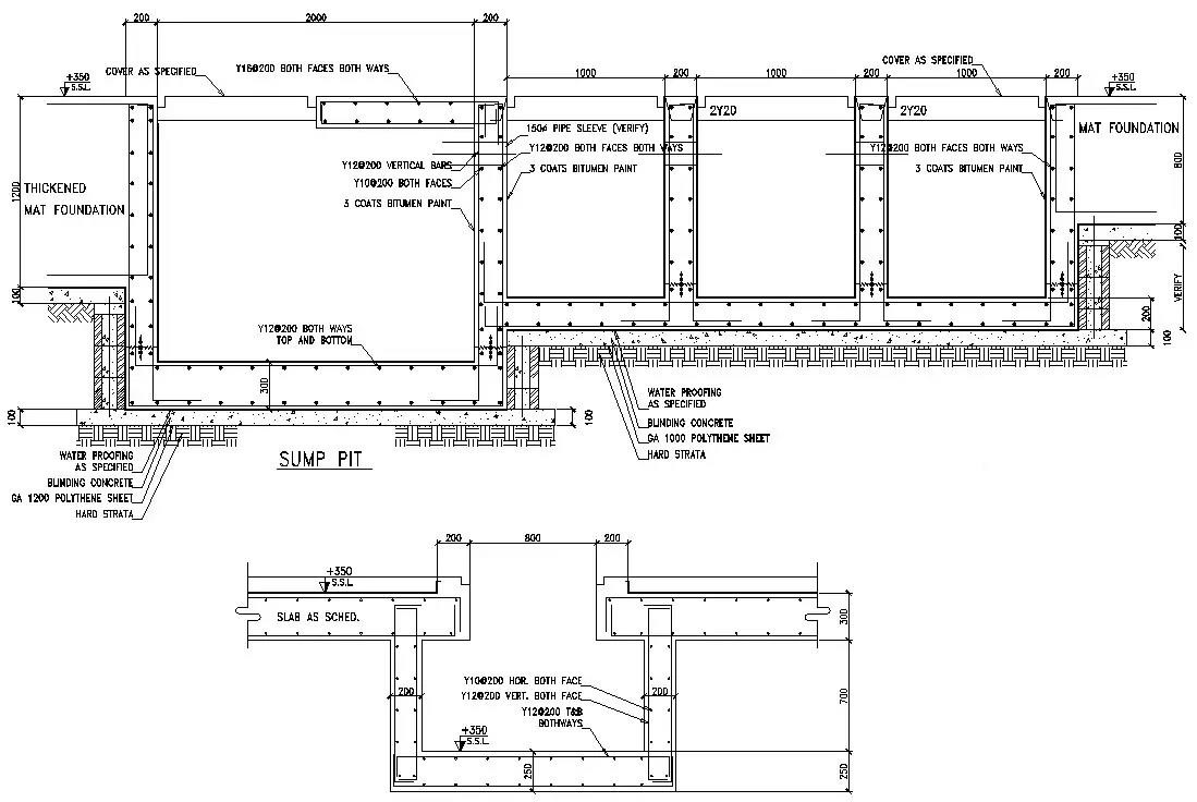
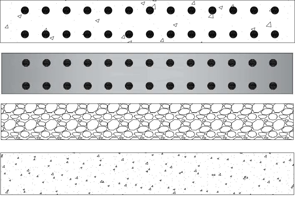
Concrete slabs of sump pits require a high-volume of construction materials and operations over the life cycle. This project aims to select a proper type of sump pits and factory structure that can significantly contribute to the sustainability of concrete projects. Conventional Concrete (Conv. C), Precast reinforced concrete (PRC), Rock-Filled Concrete (RFC) and Roller-Compacted Concrete (RCC) are four concrete sump pits construction methods evaluated on the construction of the base slab (a component of a concrete sump pit) in this project as shown in figure 2
2. Goal and scope of the assessment
The main goal of this project is to compare the environmental effect of RCC, RFC, and Conv. C methods during the lifespan of the concrete slab. To achieve this purpose, the boundary for the LCA study is set for material production, transportation, operation, and maintenance, which is described in Fig. 3. Materials in this study include all of the concrete and steel compositions and fossil fuels.
The cross-sections of the concrete slab in four different construction methods are shown in the figure below:
3. Life-Cycle timeline
To create the timeline of design options, the materials consumption during the major interventions, such as repairs, replacements, and maintenance works are taken into account. Generally, Concrete repairs can be divided into four broad categories [5, 6]:
• Sealers and coatings, which can be used to protect concrete and to repair surface damage and small cracks (used frequently for maintenance)
• Thin repairs, which are less than about 2 inches thick and do not encompass any reinforcing steel
• Thick repairs, which typically extend behind at least one mat of reinforcing steel or are at least 6 inches thick
• Crack and water leak repairs
Coating compounds (CC) are used to prevent the flow of water into or out of concrete. For thin repairs, the dry-pack (DP) method can be used on small holes in new concrete. Thick repairs include shotcrete (S) and Concrete Replacement (CR). To repair crack and water leaks, resin injection (RI) is used. The frequency of each intervention for different design options is listed below. In this study, thick repairs are counted as the main interventions.
4. Life Cycle Inventory and Analysis
In this section, the life cycle inventory of different materials used in the construction of the concrete sump pit is studied. The main material in each method is cement, which is an energy-intensive material. The emission factor of the cement used in this project was calculated based on the Intergovernmental Panel on Climate Change’s (IPCC) 2006 guidelines for national greenhouse gas inventories. Regarding other materials, the emission factors were obtained from various resources, including the European Reference Life Cycle Database (ELCD) 2009, the United States Environmental Protection Agency (USEPA) 2000, the Civil Concrete Committee in Japan 2002, and the Chinese Reference Life Cycle Database (CLCD) 2012 [7, 8, 9, 10, 11].
The table shows the emissions generated by manufacturing raw materials for the four different construction methods. The unit amount represents the quantity of the raw materials required to produce 1 cubic meter of concrete.
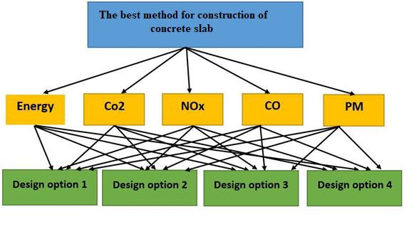
5. MCDM – Analytic hierarchy process (AHP)
AHP is one of the multi-criteria decision-making methods enabling decomposition of a complex decision problem and forming a ranking of the alternatives considered. For this study the AHP decision-making approach is shown as follows:
A set of options for each issue are compared for these criteria. In other words, for a selected criterion the decision-maker specifies a range of options that are further discretized. The decision-maker is required to perform the comparisons using a ratio scale, where the ratios indicate how many times one element is better or worse in terms of preferences.
6. MCDA – TOPSIS
In this section, the Topsis method is implemented by identifying weights for each criterion, normalizing scores for each criterion, and calculating the geometric distance between each alternative and the ideal alternative, which is the best score in each criterion.
In this step, we form the decision matrix of criteria and options. In this step, we must also specify the positive and negative criteria. Positive criteria are profitable, meaning that the more they are, the better, and negative criteria are costly, and the lower they are, the better. According to the research criteria, energy, CO2, NOx, CO, and PM are all negative criteria. In the case presented below, Energy gets the higher weight which means is the most important while PM gets the lower weight which means that is considered less important.