Explanation of the System:
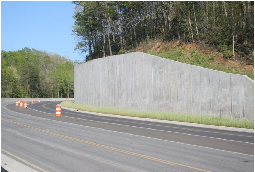
A retaining wall is a rigid wall to support soil laterally so that it can be maintained at different levels on the two sides. The main purpose of a retaining wall is to prevent soil erosion. Soil erosion is a common phenomenon found especially in hilly areas where there is slop in the ground surface. The probability of soil erosion is increased when there is a flood or rain, and the importance of a retaining wall comes at this point. The major structural elements of a retaining wall are the vertical wall, base slab and shear key.
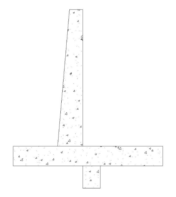
The maintenance interventions and life-cycle analysis of a prefabricated concrete retaining wall are carried out. The cross-section of the system is shown in the below figure 2:
Retaining Wall:
The analysis is done for a 10 m-long retaining wall with a shear key at the base.
- Base slab width—1.5 m
- Base thickness—0.25 m
- Shear key Cross-section Area—0.1 m2
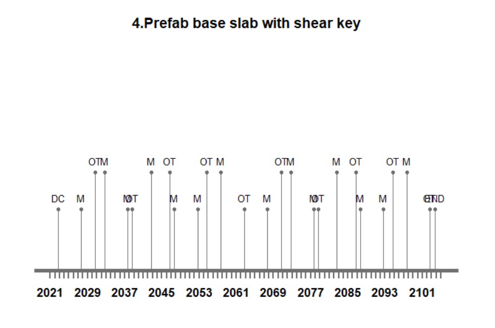
Maintenance:
The expected lifetime of the retaining wall is 81 years, and during this period regular maintenance should be carried out over the system. For the creation of the lifecycle timeline, the following maintenance criteria were used.
OT = 8, M = 5, END = lifetime
Where, OT – Overturning check which is needed to be done every 8 years, M – Maintenance with a frequency of 5 years and END – End of life. The below figures show the timeline generated for each design option through the RStudio software.
Embodied Energy and Emissions:
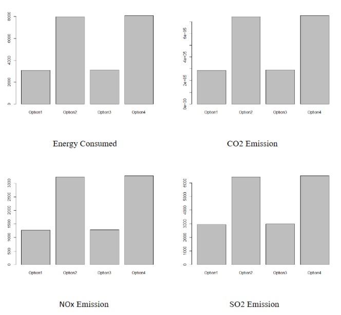
The environmental impact of the construction and maintenance of the retaining wall is done for the LCA. Environmental impacts that were considered are the following:
- Energy consumed
- CO2 emissions
- SO2 emissions
- NOx emissions
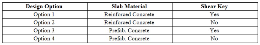
The energy consumption and emissions are analysed for four design options, considering the shear key as a non-mandatory element. The materials taken for the construction of these elements are prefab concrete and cast-in-place reinforced concrete. The table below shows the list of design options.
The energy consumption and gases emitted during the manufacturing and maintenance process for these design options are shown in the below graphs.
References:
- Ameni Boumaiza, Antonio Sanfilippo, Nassma Mohandes (2022). “Modeling multi criteria decision analysis in residential PV adoption”
- TOPSIS method for Multiple-Criteria Decision Making (MCDM) – GeeksforGeeks
- Phil Purnell (2013). “The carbon footprint of reinforced concrete”
- Marceau, M., Nisbet, M.A. and Van Geem, M.G., 2007. “Life cycle inventory of portland cement concrete. Portland Cement Association”