STEP 1: Defining the Classes and Class Hierarchy
For the integration context of the energy supply of a city, new classes such as “Energy Generation” and “Energy Transportation” are created and the Ontologies of the individual systems added as subclasses (s. Fig.1).
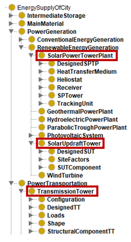
Fig.1: Extract of class hierarchy showing the integration of the three individual systems into one ontology for the energy supply of a city [taken from Protégé]
All three individual systems contain the concept of materials summarizing the used materials for the individual components of a particular system. Thus, a superclass “MainMaterial” is created including all used materials for the systems within the combined Ontology (s. Fig. 2).
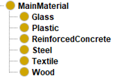
Fig.2: Extract of class hierarchy showing the superclass “MainMaterial” with its subclasses [taken from Protégé]
For the Updraft Tower and the Solar Power Tower Plant the concept of storing the surplus heat of the day correspond. Thus, a superclass “IntermediateStorage” is created containing a “MoltenSaltStorage” for the Solar Power Tower Plant and a “WaterStorage” for the Updraft Tower (s. Fig.3). Both storage types can be categorized as a thermal storage and different types for a chemical and mechanical storage are added. All types are commonly used in the context of sustainable energy technologies and provide design alternatives for the storage of different energy forms.
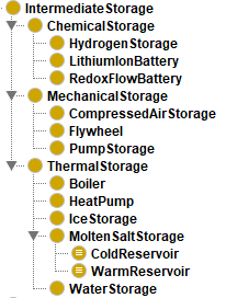
Fig.3: Extract of class hierarchy showing the superclass “IntermediateStorage” with its subclasses [taken from Protégé]
Besides, all three individual systems contain the same concepts, such as “Tower”, “Foundation” or “StructuralComponents” as subclasses of the individual systems. Here, it was considered to combine the intersecting concepts into one superordinate class. As a result, the ontologies for the individual systems would have been split apart, so that it would no longer be clear which component is needed for which particular system. Moreover, these concepts were already specified according to the requirements of each individual system by either naming the concept characteristically (e. g. “IndividualFoundation” for the Heliostats of the SPTP) or by describing the concept with certain design option as subclasses, which are eligible for this system (e. g. 8 design option for the foundation of a Transmission Tower). A breaking down of the individual ontologies would lead to a totally different overall ontology, which no longer would suit the integration context as well as the aforementioned purpose and scope of the combined Ontology. Therefore, only the names of the same concepts are adapted by adding an abbreviation, like “TT” for Transmission Tower, “SUT” for the Solar Updraft Tower and “SPTP” for the Solar Power Tower Plant (s. Fig.4). By this, concepts or components can be easily related to the individual system, they are part of, and confusions are prevented.
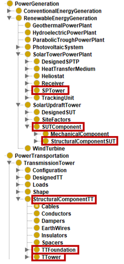
Fig.4: Extract of class hierarchy showing the same concepts for the different individual systems, which were renamed for terms of validation [taken from Protégé]
The classes of the individual Ontologies are created in a bottom-up development process. Moreover, all classes at the same level are disjoint to make sure that an instance of one class cannot be an instance of another class. As this ontology only represents a section of a real entity, it can be extended and refined with much more data.
STEP 2: Defining the Object Properties of Classes
Based on the developed class hierarchy, relations between the classes and their inverse are defined by implementing object properties. As Fig.5 shows, prefix “has” and the inverse “is … of” are added to the class names. In this way the following object property hierarchy develops.
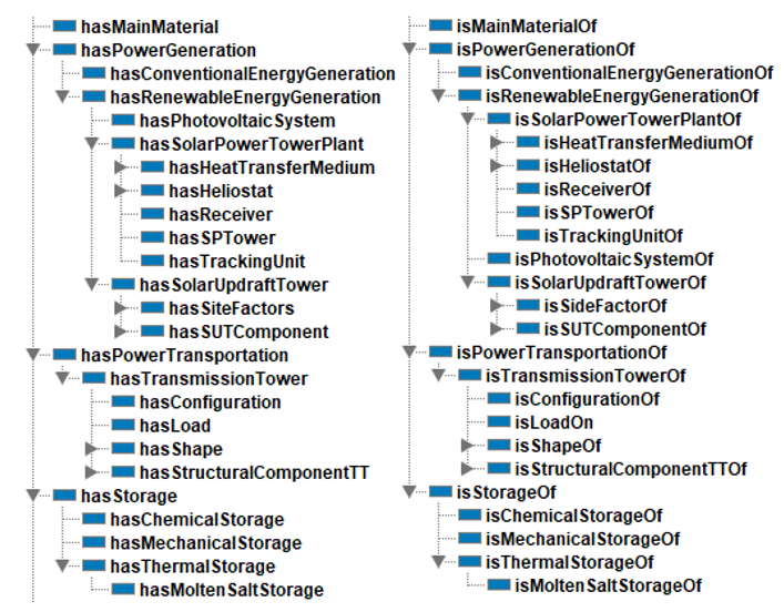
Fig.5: Taxonomic hierarchy of object properties [taken from Protégé]
STEP 3: Defining the Domain and the Range of the Object Properties
The domain of an object property describes the classes which can be related (input), while the range describes the class, as well as all it subclasses, which the object property is related to (output). For the inverse of the object properties the domain and range are reversed. In the following Fig.6, the defined domain and range for a few object properties and their inverse are represented exemplarily. They can be read as “[Subclasses or Individuals of the class] EnergySupplyOfCity (domain) hasMainMaterial [from class] MainMaterial (Range)”.
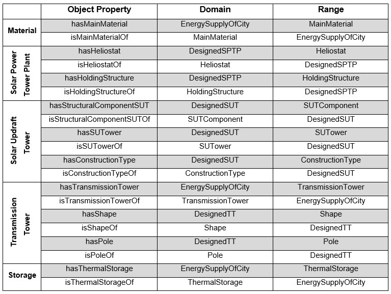
Fig.6: Summary of the defined domain and range for a few object properties [authors’ table]
STEP 4: Creating Instances and Design Options
The existing design options of every individual system and the related individuals are integrated into the combined Ontology and extended to suit the integration context. This means, that data property assertions of certain individuals are changed in their value or replaced by another according to the predefined input parameters within the integration context. By this, three configurations for the Renewable Energy Park were implemented, each representing a virtual city with a different number of inhabitants and energy consumption per capita. All further input parameters for these virtual cities are summarized in Fig.7. Except the design options of the individual systems, these input parameters are implemented as data property assertions for each configuration (s. Fig.8).
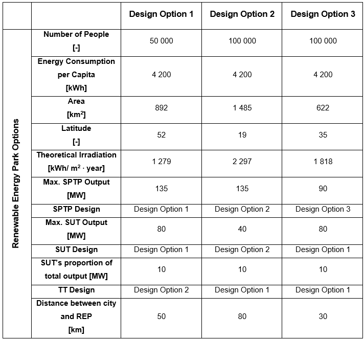
Fig.7: Summary of input parameters for the implementation of three Renewable Energy Park Configurations [authors’ table]
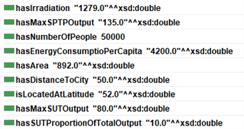
Fig.8: Data property assertions for the individual “REPOption1” [taken from Protégé]
STEP 5: Defining Properties Restrictions
By the definition of property restrictions, differences and limitations as well as similarities between the individuals of certain classes are defined. As the afore defined domain and range do not provide any constraints (s. STEP 3), the definition of property restrictions are needed. To the existing property restrictions for the “Designed”-classes of the individual systems (s. Fig.9), further restrictions are added or specified in order to suit to the integration context.
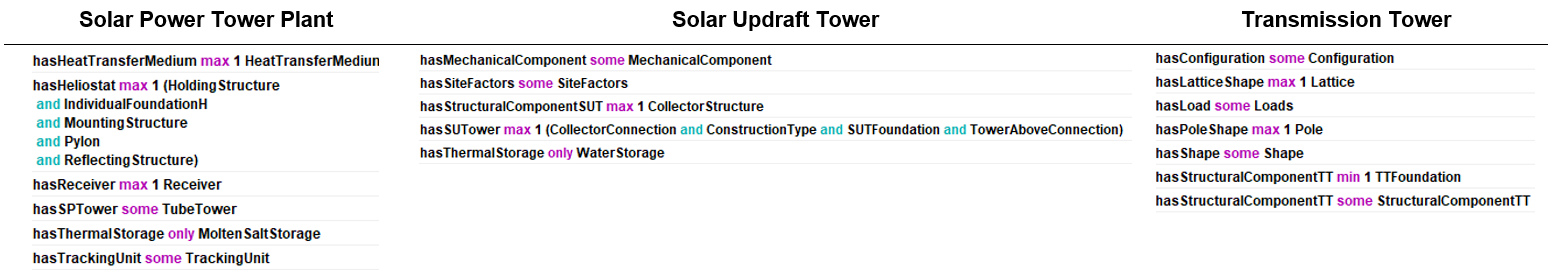
Fig.9: Summary of properties restrictions for every individual system [taken from Protégé]
An example for a specification of a restriction is done for the SPTP by saying that a SPTP does not just have a tower from SPTower-class, but rather the specific type of a “TubeTower”. Thus, all other tower types are excluded for the defined design options.
![]()
An addition is e. g. done for the SPTP and the SUT by determining a thermal storage type. The universal expression “only” implies that a SPTP or SUT does not have to have a thermal storage, but if they have a storage, then the SPTP comprises a molten salt storage, while the SUT comprises a water storage.
![]()
Besides these general property restrictions, different individuals are assigned to each design option of the individual systems. These individuals define the characteristics of the design options and make them distinguishable. To establish a connection between the MainMaterial-class and the certain components of the individual system different material types, such as steel or reinforced concrete, are implemented as individuals and related to the particular design option by nominal expressions (s. Fig.10).
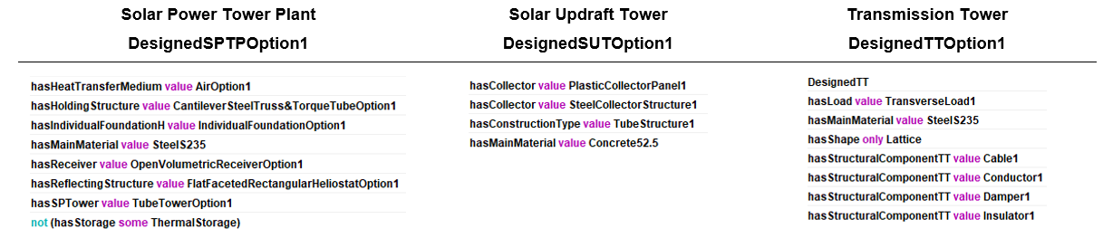
Fig. 10: Summary of nominal properties restrictions for one design option of every individual system [taken from Protégé]
Finally, existential restrictions as well as one negation are implemented for the configurations of the Renewable Energy Park (s. Fig.11). For each of this configuration one design option of the individual systems is related to by a nominal restriction (Fig.12).
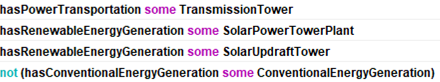
Fig. 11: Summary of properties restrictions for the Renewable Energy Park Configuration [taken from Protégé]
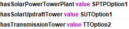
Fig. 12: Summary of nominal properties restrictions for one design option of every individual system [taken from Protégé]
See also:
Introduction to Combined Ontology
Or main topics:
Integration Context and Individual Systems