Introduction
These days, interest in devices that generate less environmental pollution is increasing due to the influence of climate change. The air-cooled chillers installed in buildings are also making great efforts to generate less environmental impact.
In this report, I want to find out the difference in environmental impact according to the number of air-cooled chillers. To this end,
1) Introduction to HVAC system and air-cooled chiller
2) parameter definition
3) scope and goal of this report definition
4) Three different options are defined, and each characteristic is explained
5) life cycle inventory and timeline setting
6) life cycle analysis is performed.
Through this, we will find a way to generate less environmental pollution throughout life when installed in a building and analyze why it shows such results.
1. HVAC system & Air-cooled chiller
HVAC stands for Heating, Ventilation, and Air Conditioning, and it refers to the technology of indoor and vehicular environmental comfort. They are designed to provide and maintain thermal comfort and acceptable indoor air quality. These systems control the temperature, humidity, and air quality in buildings.
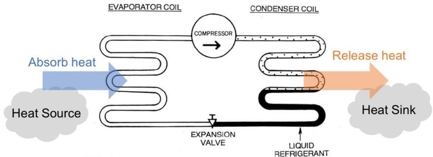
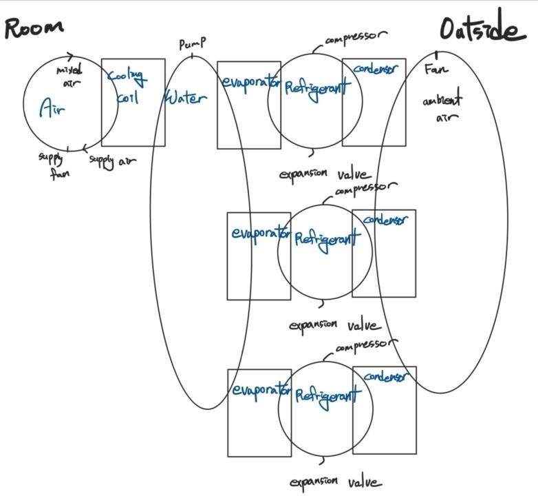
An air-cooled chiller is a specific component within an HVAC system. Chillers use electricity to remove heat from the building through the chilled water loop. An air-cooled chiller is a type of chiller that uses ambient air to remove heat from the refrigerant. It typically consists of a compressor, condenser, expansion valve, and an evaporator.1 Refrigerant repeatedly compresses and expands through the valve, supplying cool to the water cycle through state changes, and the water cycle cools the air inside the room through heat exchange by using the cooling coil. A simple illustration of the principle of the air-cooled chiller is as shown in Fig. 1.
2. Define parameter
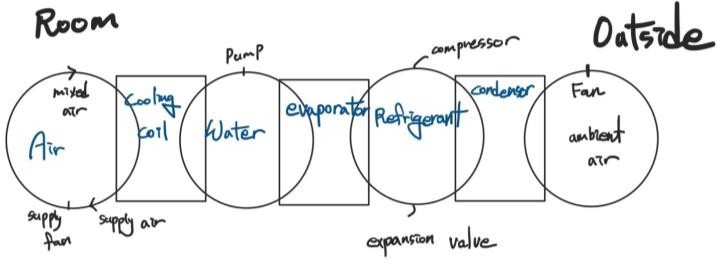
A simple expression of the air-cooled chiller is as shown in Fig. 2 below.
 x
x
The ‘roughly calculate materials quantities’ for each element are as follows.
Chiller – It absorbs heat generated inside the building or in the factory through a refrigerant and compresses this refrigerant to increase the heat. Usually, two or more compressors are used in one building. If two compressors are used and one compressor is broken, the overall performance is reduced by 50%. In addition, the number of chillers varies depending on the cooling capacity of the entire building.
Cooling Tower – A cooling tower uses water to release the heat that cold water has into the atmosphere. The number of cooling towers installed in a building may vary depending on the size, cooling and refrigeration requirements, and design of the building, but in general buildings that are not large commercial or industrial buildings, one cooling tower is used.
Coil – Helps to transfer heat and helps to transfer heat in the air and water inside a room. A room is small enough to cover with one coil, but if the room is large or has several rooms, several coils are required.
Pump – helps to circulate water. One is used for every water cycle.
Fan – acts to circulate air. Multiple fans can be used in one chiller, as shown in Figure 3, and the number of fans is determined to circulate enough air. This fan not only helps the outside air meet the condenser more, but also helps the air inside the room meet the cooling coil more, thereby controlling the temperature inside the room.
Damper – responsible for controlling the overall amount of air conditioning, and one is usually used. Duct – deliver cold air from the chiller to the room.
Air-cooled chiller can be divided into three parts, and it is summarized in a Table 1.
| Central equipment – Chiller, Cooling Tower |
| Distribution system – Coil, Pump, Fan |
| Delivery & control – Damper |
Table 1
3. Define scope & goal
Goal of the study
The goal of this study is to quantify the impact of air-cooled chiller on the environment. To this end, the report is adopted a gate-to-gate LCA methodology. The conclusion of this study is to help policymakers and assert manager make informed decisions that can ensure the sustainability of the environment. Therefore, this report evaluates the environmental contribution due to the energy used during the phase of use of air-cooled chiller systems. When evaluating environmental benefits, this report compares the results derived from the LCA analysis.
System Boundaries and Limitations
Due to the lack of reliable data, the system boundaries considered in this study included a 25- year use phase during the life cycle of the air-cooled chiller but did not consider any other steps. Furthermore, numerous LCA studies on energy systems have shown that the use phase has a more dominant environmental impact compared to other stages considered is negligible.23 The system boundaries in this study are constructed in a way that quantifies the amount of electricity consumed. Indirect emissions from the combustion of fossil fuels in power plants and systems related to the production of coolant, as well as indirect emissions from the combustion of fuel and other chemical emissions from the power plants, were not considered in this study.
The scope and the boundaries of the assessment are presented in the figure below.
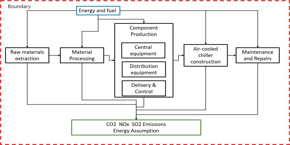
This focuses on the decisions practitioners need to take when designing the air-cooled chiller in the building. They should design the optimal cooed system for the building based on the scope and boundary as shown in the figure above.
4. Different Design Options
1. Common Method
The first method is presented in Fig. 2 above. One huge system is responsible for the cooling of the entire building. This method has the advantage of installing only one compressor, expansion valve, and evaporator, and the advantage of installing a chiller in a small space due to reduced space occupancy. In addition, maintenance costs are incurred for one product during maintenance, so maintenance costs are relatively low. However, since the entire system must be turned on to cool the building, there is a disadvantage that the entire system cannot be used if one part is broken.
2. Whole Systems
The second method is to manufacture several whole chillers. All parts of the air-cooled chiller were made of parts with 1/3 the capacity. The total capacity that the chiller can cool is the same, but when a small amount of cooling is required, only one or two chiller is operated without having to turn on the whole chiller, saving energy in this process. However, as the product is three times, the initial installation cost and maintenance cost increase, and more space is required.
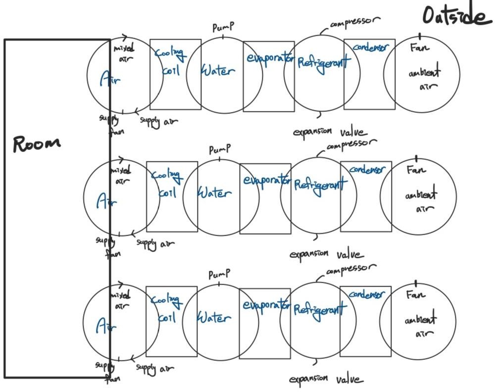
3. Refrigerant Loops
It can be said that it is the middle point between the first method and the second method. We tried to take only the advantages of methods 1 and 2 by producing three Refrigerant loops.
5. Life cycle inventory
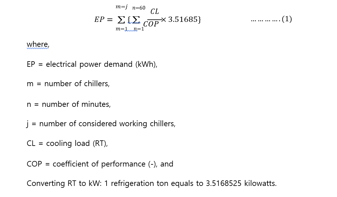
The mathematical formula for estimating the amount of EP used by the cooler per hour is shown in Equation (1). This equation is made in one study. Operation data of four ECC systems were acquired and used to define the characterization of the system unit in terms of estimating its environmental impact. Data used in building the LCI analysis were obtained from plant technicians, technical datasheets of the unit components, and literatures.
6. Life cycle timeline
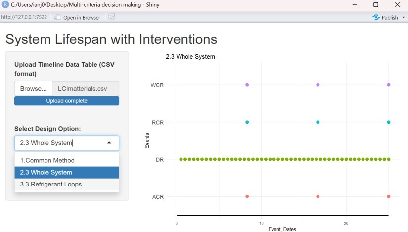
Table below is the list of interventions with frequency of occurrence for each design option. Common method has one refrigerant-cycle, water-cycle, and air-cycle and all these lifespans are 25 years. But 3 Whole System method has three cycles, so lifespan is reduced by one-third. 3 Refrigerant loop method has 3 refrigerant loop and only lifespan of refrigerant loop is reduced by one-third.
By using the application uploaded in the tub cloud, the results are as shown in the figure below.
7. Life cycle analysis
The result values could be obtained through the equation (1), Table 3, and ‘LCA Assignment2 Training’, and the results are shown in the following figure.

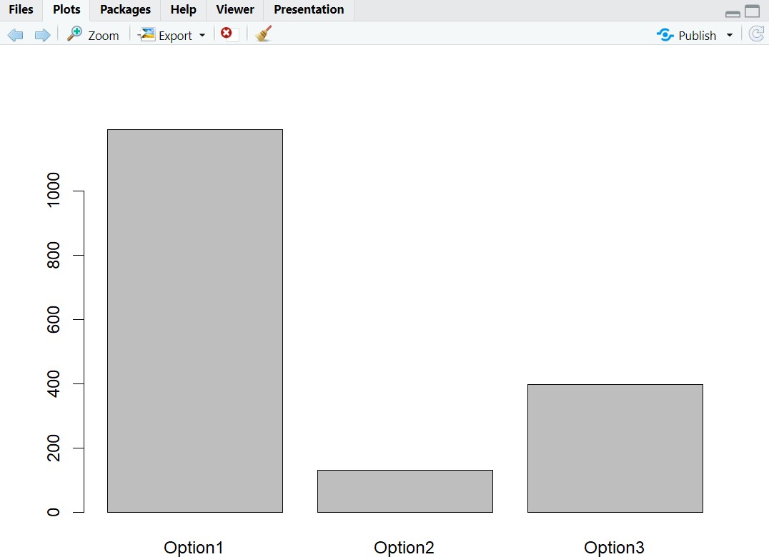
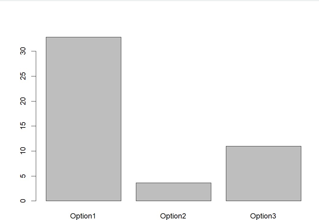
Figure 7 is CO2 emission for different design options and Figure 8 is NOx emission for different design options and Figure 9 is SO2 emission for different design options. Everywhere, the emission of option 1 is the highest and the emission of option 2 is the lowest. Through this, it can be seen that the effective method of installing air-cooled chiller is to install several small chillers as shown in option 2.
Home Page | Maintenance Strategies | Life Cycle Analysis | Multi Objective Optimization