1. Design Challenge
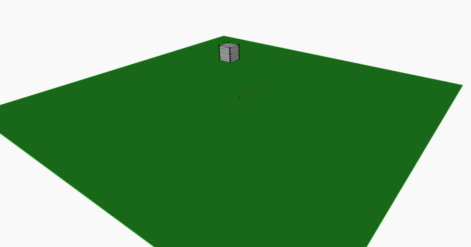
A major challenge in the modern world is the availability of land for new infrastructures, therefore we have to utilise the existing infrastructure. Combining existing structures with new ones will play an enormous role. Creating relations between the different systems is the major integration challenge. Starting point for this was an area with an existing, vacant building with the dimensions of B x W x H = 20m x 20m x 21m – shown in Figure 1. To make it usable again it was equipped with the prefabricated facade panel. The second high-rise building and the stadium were integrated into the overall system depending on their capacity. As engineering challenge is the combination to a sports facility center defined, with a stadium, a new residental building and a retrofitted building used as an office block.
2. High-Performance Criteria:
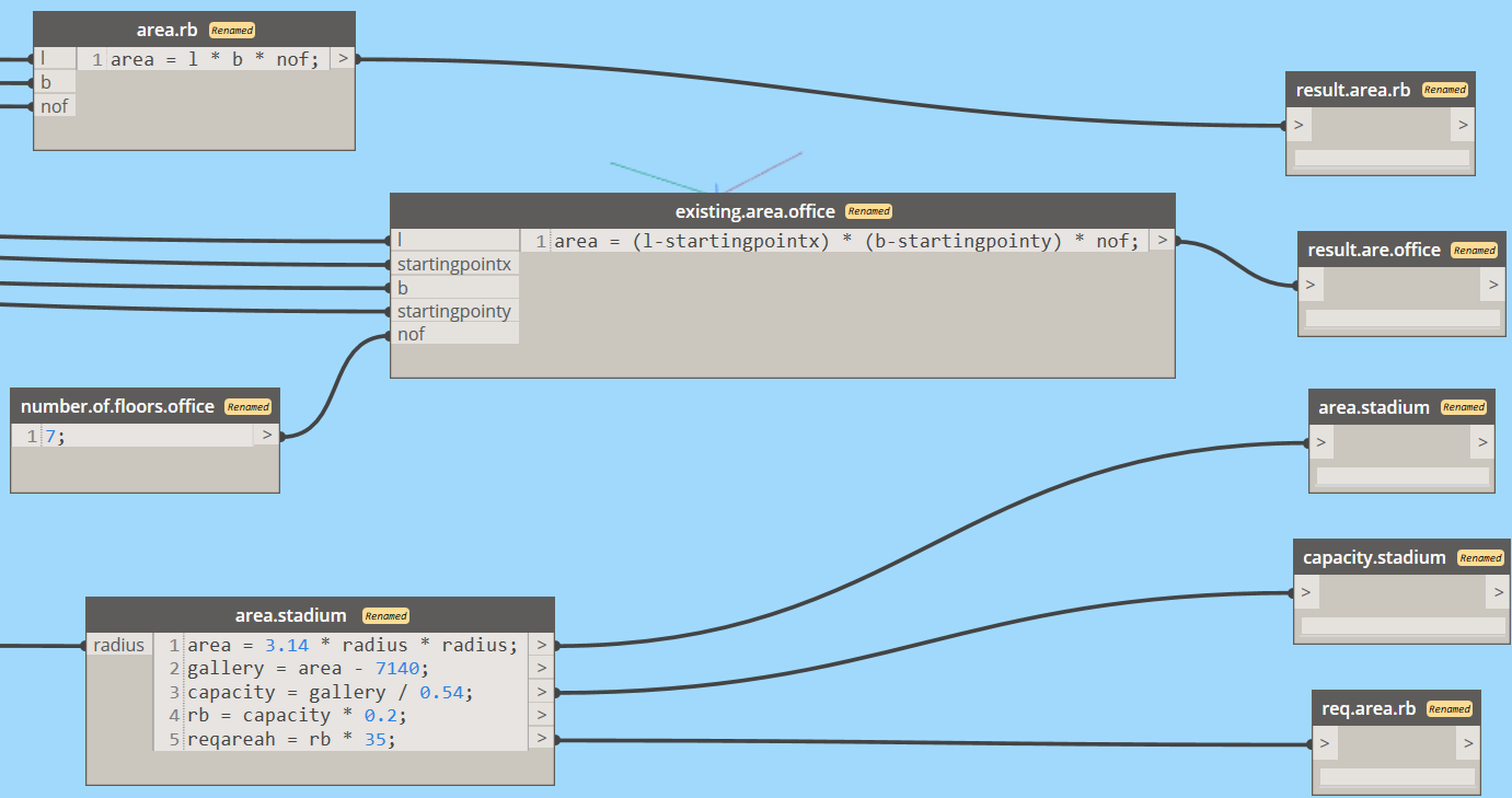
One of the key features of a football stadium is its holding capacity. Keeping this in mind the High-Performance Criteria of the integrated system was defined in such a way that, 20% of the total capacity of the stadium should be accommodatedby the residential building. The capacity of the stadium was calculated using bleachers capacity [1]. The area of the building was found using the length, width and the number of floors. The capacity for the residential building was calculated using 35 m2/person [2]. An excerpt of the calculation is shown in Figure 2 – the whole calculation is shown in the parametric model. The Bleachers capacity says that the width of a seating is 24 inches and has around 3 foot of length. Using this information the area required for one seating is 0.54 m2. The total area of gallery can be calculated by subtracting the area of the football filed (7140 m2) from the total area of the stadium (i.e. total area – 7140). Now by using 0.54 m2 as the area for one seating we can calculate the rough capacity of the stadium. The area of the building can be found by the floor area and the number of floors. The capacity of the residential building can be found by using the minimum area required for one person i.e. 35 m2. This area includes the net area required by one person for a living space, bedroom and bathroom. Now by comparing the capacity of the building and the required capacity of the building we can understand the high performance of the system.
Another High Performance Criteria included in the combined model was slenderness ratio, which was designed in the individual system of High-Rise Building. As limit value there is 1:7 = 0.142. For energetic renovation concepts there is always the need of reaching goals according to reducing energy consumption. One huge factor is the heat transfer coefficient, which is important for the feeling inside of the building as well as the ventilation and heating behaviour. This criteria is only used for the retrofitted office building and not for the new one. As said in the individual assignment of the prefabricated facade panel, the goal is to reach a value of U < 0.13 W/(m²K).
3. Logic of the parametric model
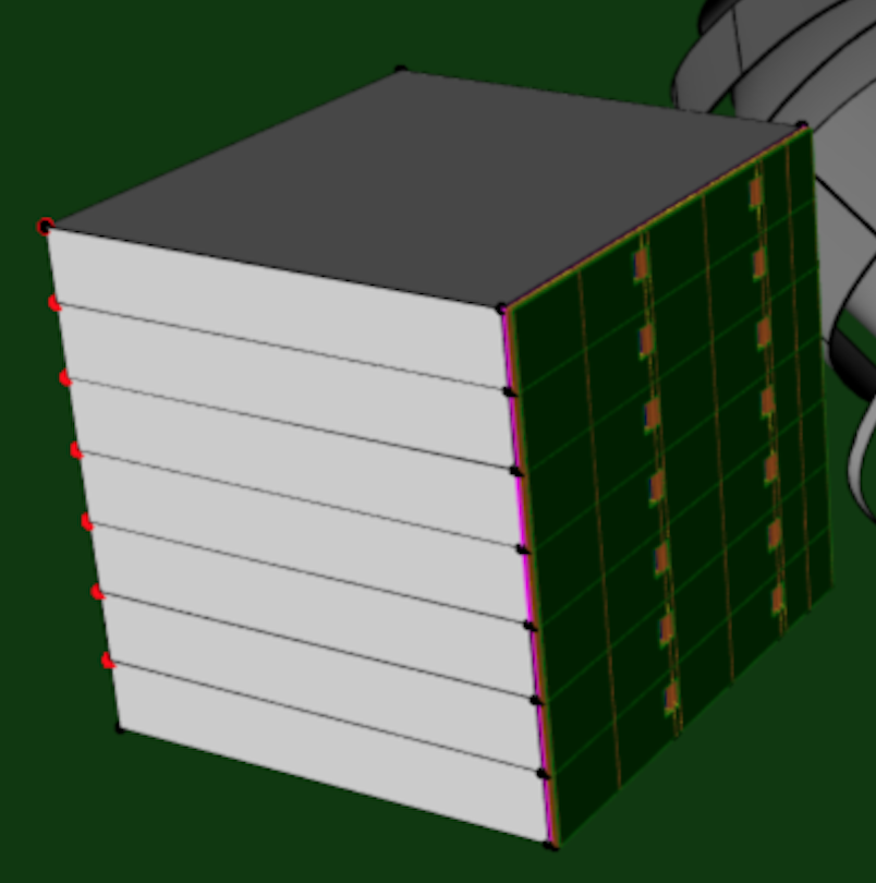
The model was combined using Revit Dynamo. The stadium was placed in the centre and the residental building were placed adjacent to it. The existing office building was integrated with the prefabricated façade panel. The following figure shows the Dynamo interface for the integrated model.
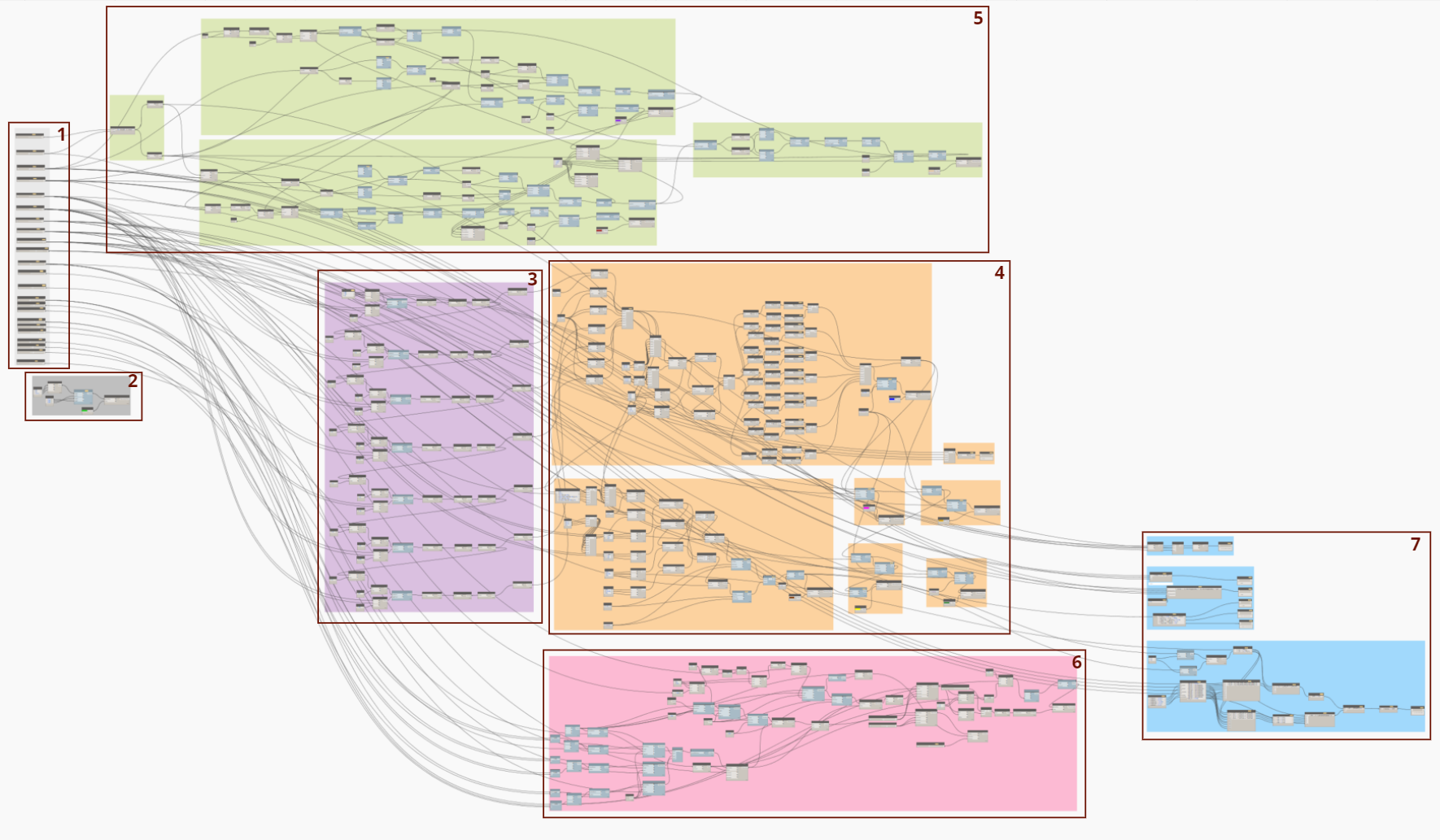
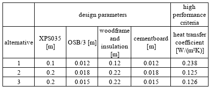
The integration of the façade panel into the existing building (part 3) is executed by attaching it to one side of the structure. The complexity of the code necessitates that only one side of the building be fitted with the prefabricated facade panel. The layer thickness of the façade can be adjusted using input parameters, while the heat transfer coefficient can be automatically read in accordance with the high performance criteria (part 7).
To optimize the use of available space while avoiding constraints on the existing building, the stadium (part 6) was designed with a maximum radius that accommodates sufficient space for the building. The stadium radius range is between 60 and 100 meters. The new residential building (part 5) is positioned in such a way as to not obstruct either the stadium or the office building. As a result, its maximum length and width is limited to 50 meters, with a maximum height of 65 meters. Part 7, which calculates the required capacity of the apartment building, takes into account the radius of the stadium to determine its capacity.
4. Design Alternatives
According to the high performance criteria defined in chapter 2, several design alternatives for the dependency of the residential building and the stadium are compared in Table 1. To explain the number of floors according to the building height: 9 floors = 25 meters ; 22 floors = 65 meters.
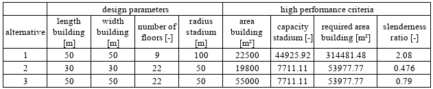
The results show that only option 3 reaches the goal of the required area for the residential building. The other alternatives are not sufficient. The slenderness ratio of the three options are efficient for every alternative and reach the goal of 1:7. For the energy retrofit of the existing building the consideration of the different façade solutions was made. Alternative 2 performs best, but also shows the highest material usage related to the layer thicknesses. It shows that an increase of the insulation layers has the greatest influence on the reduction of the heat loss. A change of the cladding shows only minor changes.
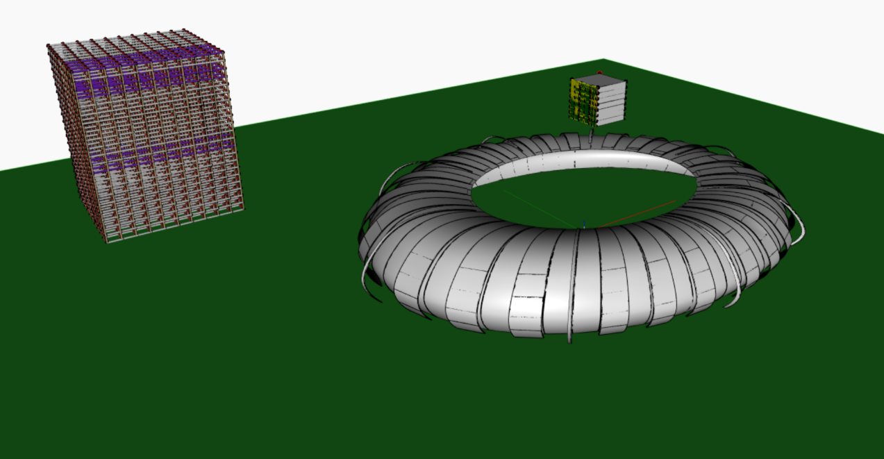
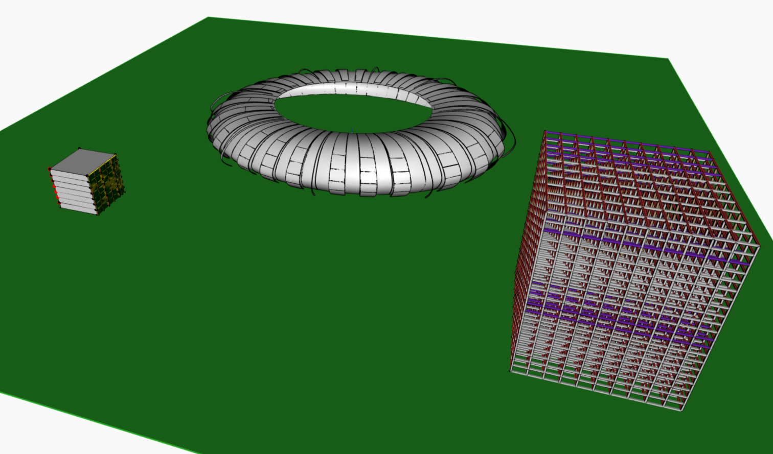
Finally, the best solution from the design alternatives is shown in Figure 4. The one picture of the retrofitted existing building shows the dependency of the first high-rise and the facade.
Download the parametric model: combined-parametric-model-sports-facility-center
References
[1] https://www.preferred-seating.com/blog/how-to-calculate-seating-capacity-for-bleachers
[2] https://www.sihmind.mp.gov.in/Uploaded%20Document/jer/notes/facilty%20planinng.pdf
Go to the Ontological Modelling: Sports Facility Center: Combined Ontological Modelling