Introduction
The context of integrating the four individual system (Student residence, Residential building, Restaurant, and Gymnasium) was combining them into a sports complex. The gymnasium will be the main sporting venue. The two residence systems will be used to accommodate students and employees. And we will have a restaurant where everyone can enjoy while in the sports complex. In addition to the four systems, additional elements were required to organize the sports complex. That includes environmental elements such as the landscape and road.
Integration Challenge
1. Building the Environment
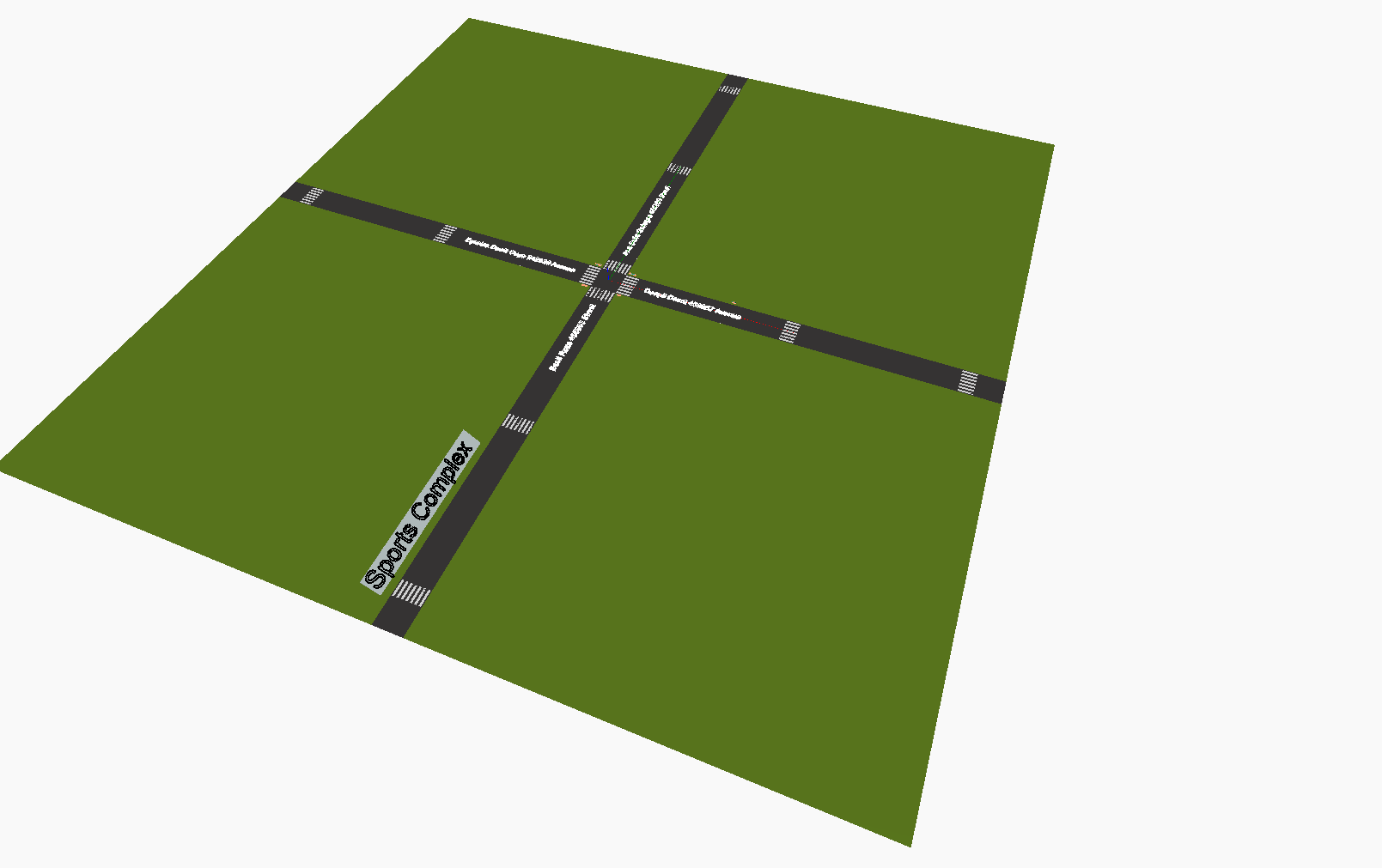
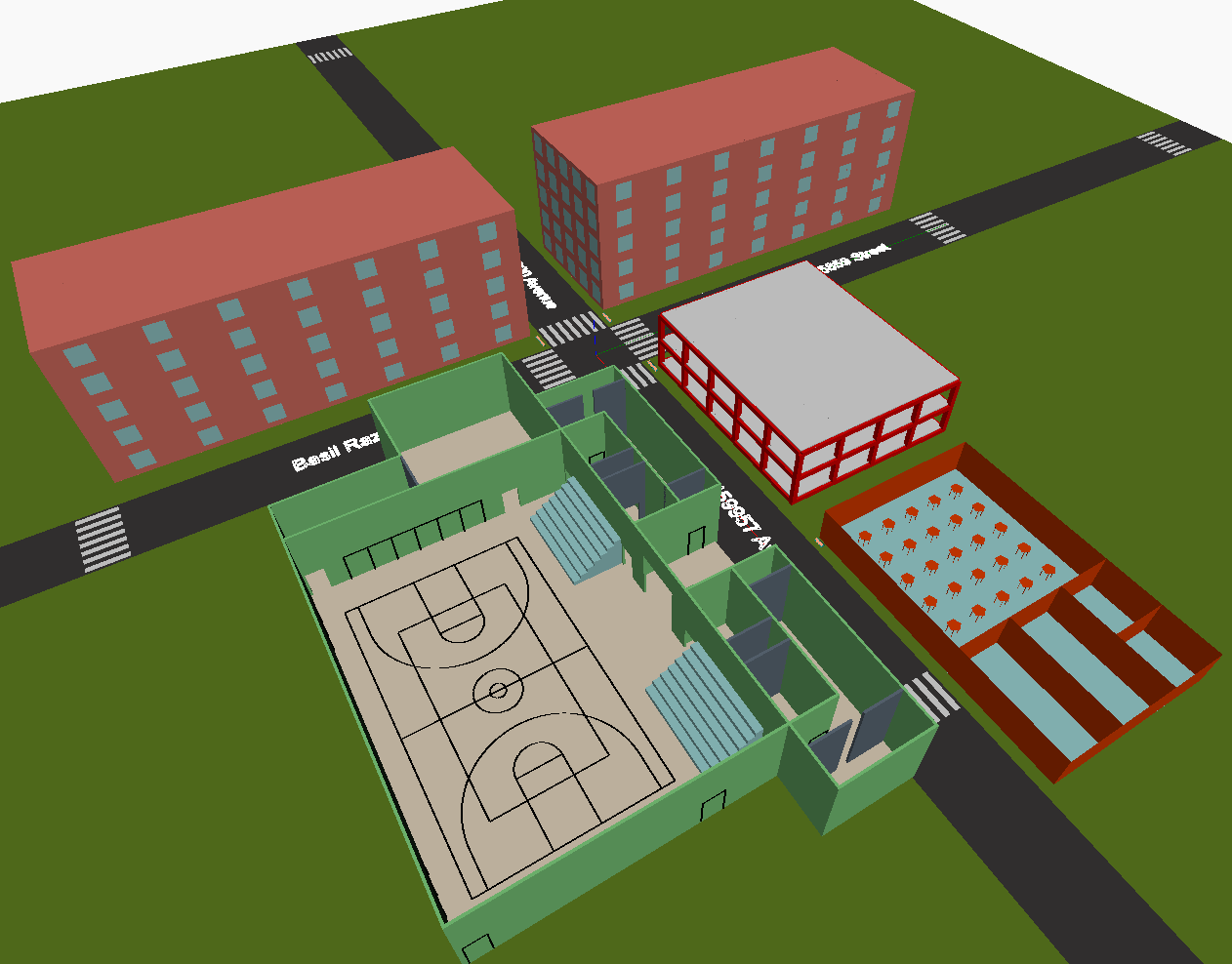
Ahead of bringing the four individual civil systems into a single environment, we had to built that environment. The environment was supposed to be a sporting complex. We created four roads that run in four directions, so each civil system has access to roads. The landscape is shown on figure1.
After the landscape was ready, all the dynamo script was copied into it. The challenge with this was originally that all models were modelled to start at the origin of the X, Y, Z coordinate. This meant, when the models were brought into a single model, all of them were overlapping each other at the origin of the X, Y, Z coordinate. To mitigate this challenge each parametric model was reconfigured and moving features were introduced. Using these features, each model was moved into the right place on the landscape.
2. Integrating individual systems
The main challenge when integrating the four individual systems was that each of these systems had different design parameters. Each parametric model was controlled as follows:
- The student residence parametric model is controlled by specifying the ensuite room dimensions.
- The gymnasium parametric model is controlled by parameters that manipulate number of seats.
- The residential building parametric model is controlled by adjusting the footing size and the building size.
- The restaurant parametric model is controlled by selecting a configuration type for the restaurant.
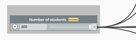
As it can be seen from the above list, at the start, the four systems didn’t have any common design parameters. Therefore, to combine these and create a parametric model of a sports complex, we had to devise a method where all four systems were controlled by a common design parameter. After having discussion about this topic, we decided to create a new node labeled ‘Number of Students’ the main design parameter of the integrated system (sports complex). To accomplish this, each model needed to be modified and this new node was utilized as the main input. The modified work done on each system is briefly discussed on the next paragraphs.
Student Residence
The student residence is the building that accommodates students. The original model was controlled by specifying the dimensions of the building. For integration purpose a new design parameter that is ‘student number’ was added. The building was modified to have five stories with each story having 20 rooms. These will mean a single building will have 100 rooms to accommodate students. The minimum number of student the sports complex should accommodate is 200 student. As a result, a minimum of two student residence building was required. And these two buildings were placed facing each other with a road passing between them.
New dynamo nodes were added to control the number of buildings based on student number. These nodes were connected to the ‘Number of Students’ node. As the value of the student number change, the number of student residence buildings will also change in a manner that provide enough rooms to all the students. This relationship can be seen on Figure 3. The number at the bottom of the animation is number of student.
Restaurant (Student Cafeteria)
The restaurant, now turned into a student cafeteria, it was modified to accommodate 50% of the total number of students at a time. The reason for this is that not all students will eat at once in the cafeteria. Some students like to get their food packed and some like it to be delivered to their respective rooms. Some students even go outside the sports complex to have food from their favorite deli or restaurant. The cafeteria is also assumed to serve food at all times and doesn’t have any fixed time for meals. Having flexible timing instead of fixed one helps in preventing the concentration of student traffic at a particular time and the traffic peak is low.
The ‘Number of Students’ node was plugged-in into the existing nodes in the restaurant model. This was done in a manner that enabled the number of students to control the total length and width of the cafeteria which in turn affects the number of seats and the kitchen area. This change is shown on figure 4.
Gymnasium
The individual gymnasium parametric model was controlled by editing the number of rows on a seat cluster and the number of those seat clusters. The dynamo script then calculates the number of students based on those parameters. For integration purpose, that process was reversed. The number of students became the main design parameter and the number of clusters and the number of rows on those clusters were computed and modeled by using the ‘Number of Students’ node.
The result of the modification can be seen on the animation on figure 5. The animation shows the changes the gymnasium model goes through as the number of student (shown at bottom center) changes.
Single story house converted to employees’ residence
The ratio of the number of instructors/trainers/coaches required to the number of students is assumed to be 1:10 and it is also assumed that 8 of these employees’ will occupy a single floor. A floor will get added to the instructor residence for every increase of 80 students. The ‘Number of Students’ node was used to determine the number of employees.
The animation on figure 6 demonstrates the change the model go through as the student number (shown at bottom center) is modified.
Integrated Parametric Model
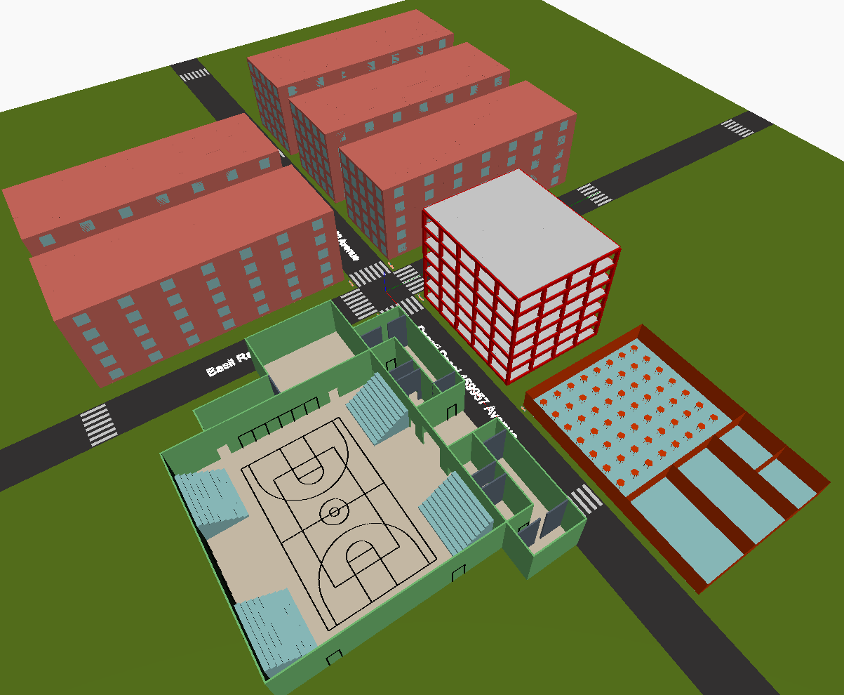
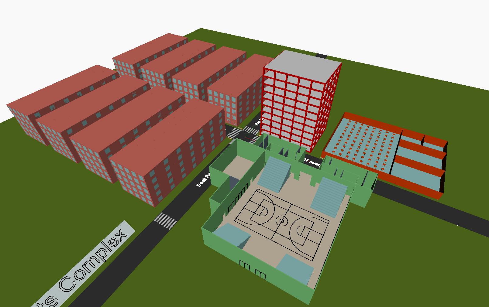
The modifications discussed on the previous sections resulted in a parametric model that is controlled by ‘Number of Students’ node. The minimum number of students the sports complex is 200 students and the maximum is 800 students. By selecting any number between these limits, the required type of gymnasium, student accommodation, employee accommodation and student cafeteria was generated. Figure 7 demonstrates the change the sports complex goes through as the number of student is changed (shown at bottom center).
Various alternatives
Any number of student capacity between the limits (200 and 800) can be selected to generate a model. However, we have selected three alternatives to present on this website.
Alternative 1: For 200 students
This alternative can be use to design a sports complex for small number of students. The resulting model is displayed on figure 8. The configuration of the four systems to accommodate this small amount of students is as follows:
- Employee residence – 2 story accommodating 20 employees
- Gymnasium – 2 stands with 7 rows (15 seat per row). 210 seat capacity over all.
- Cafeteria- 100 student seating capacity
- Student residence – 2 buildings. Each building has 5 story and each story has 20 rooms. Overall 200 rooms.
Alternative 2: For 500 students
This alternative represents a sports complex that is designed to accommodate the average number of students between the limits. The resulting model that can support 500 students is displayed on figure 10. The configuration of the four systems to accommodate this amount of students is as follows:
- Employee residence – 6 story accommodating 50 employees
- Gymnasium – 4 stands with 9 rows (15 seat per row). 540 seat capacity over all.
- Cafeteria- 250 student seating capacity
- Student residence – 5 buildings. Each building has 5 story and each story has 20 rooms. Overall 500 rooms.
Alternative 3: For 800 students
A sports complex that is expecting a large number of students can use this design alternative. The resulting model based on 800 students is displayed on figure 10. The configuration of the four systems to accommodate this large amount of students is as follows:
- Employee residence – 10 story accommodating 80 employees
- Gymnasium – 4 stands with 14 rows (15 seat per row). 840 seat capacity over all.
- Cafeteria- 250 student seating capacity
- Student residence – 8 buildings. Each building has 5 story and each story has 20 rooms. Overall 800 rooms.
Conclusion
As already discussed in the Integrated Ontology, the intended users for this model are universities, schools, and colleges that want to develop a sports complex. They can get an estimate of how many students they are willing to cater to and can choose a design option accordingly. There are various design options available in the model for the range of 200 to 800 students. If the number of students is more than 800, for example, 1000 then the model with 500 students can be duplicated. Similarly, there can be various alternative options available even for several students out of the specified range by mix and match of the model.
Apart from that, since the individual systems also work independently within the integrated system, the designers are provided with an option to choose a combination of individual systems as their requirements. In the case of an already existing institution, which might require only a combination of a few individual systems like a Gymnasium and Cafeteria, other systems like Student and employee residence can be omitted from the model.
Both these aspects make the model very versatile as it can be used for different ranges and different scenarios.
Preview of Parametric Model
By using nodes from a dynamo package called ‘MeshToolkit’ , the integrated model in dynamo was exported into a .dae format. Then this file was uploaded to sketchfab. The resulting 3D representation is presented below.
Dynamo Mesh
by Group6Pr
on Sketchfab
Download the Integrated Parametric Model
The dynamo file for the integrated parametric model can be downloaded by clicking the download button bellow . Or right click on the ‘Download Parametric Model’ button and click on ‘Save link as …’ then save the .dyn file to your computer.
Navigation