Abstract
The domain we are focusing the effort of creating a parametric model is Bridge. Bridges have evolved extensively since the construction of the first modern bridge in the 1820s. Bridges are considered masterpieces of architecture and technology and that bridge building is considered the supreme discipline among civil engineers. These bridges are made at different times with different materials. While working on this, it will have the potential to allow engineers to quickly explore design spaces, find optimal solutions within these design spaces, and to ensure that pre given design constraints are accounted for. The main foundation for developing a parametric bridge is to support the structural analysis. It has been aimed to have strong control about the design parameters to give diverse alternatives with different results. To evaluate the model, two high performance criteria are defined: slenderness ratio and estimation of construction. According to the selected high performance criteria the results are shown and compared.
Scope and High Performance Criteria
The definition of well thought out parametric models allows for the very quick generation of possible design alternatives. Quick generation, in turn, has the potential to allow engineers to quickly explore design spaces, find optimal solutions within these design spaces, and to ensure that pre-given design constraints are accounted for. The goal of this second modeling assignment is to understand the relation systematically and logically between a number of important parameters of your engineering product, its geometrical configuration and embodiment and a set of high-performance criteria.
The design parameters takes up the value from a wide range and as a result multiple solutions will be generated during the modelling. To assess the performance of the model, high performance criteria has been used and for this assessment, we have selected two of them and are as follows:-
- Headroom clearance – Headroom or vertical clearance is the difference between the highest point on the roadway to the lowest point of the structural element of the bridge above the passage. For deck bridges the headroom is unlimited. Based on this, we will calculate the lost width which is the difference of total width and the width left based on the headroom clearance condition. Even though, I have said earlier that there will be a less chance that the width of the bridge gets altered, still while on this a slight variation will be seen.
- Quantity of Material – Here we are doing the structural analysis using finite element analysis software and in order to reduce the complexity in doing so, we have selected only a small part i.e Girder. The high performance criteria we want to add to our model is the total steel weight and we will cover the case of calculating the cross section of the cross girder. We will consider this as a simply supported I section beam, on which we distribute a linear load. For the we need the load beared by the bridge.
Developing a Parametric Model
For the development of the parametric-model Dynamo Revit 2.10 had been used. The main design challenge for designing a Bridge is to find appropriate building form to meet both client requirements and building regulations. Since it is a bridge, the client will be a functional government body. The parametric model is developed in relation to the High Performance Criteria. The input parameters of the system is usually restricted by different regulations accordingly to site location and distance to neighbouring areas. The user can directly see how his choices are influencing the performance of the building, such as its width, deck elevation and T/L ratio. For the results of the high-performance criteria, it is important to always have good control over the changes. If one of the design parameters is changed, the results also change.
The Dynamo Workflow is shown in Figure 1.
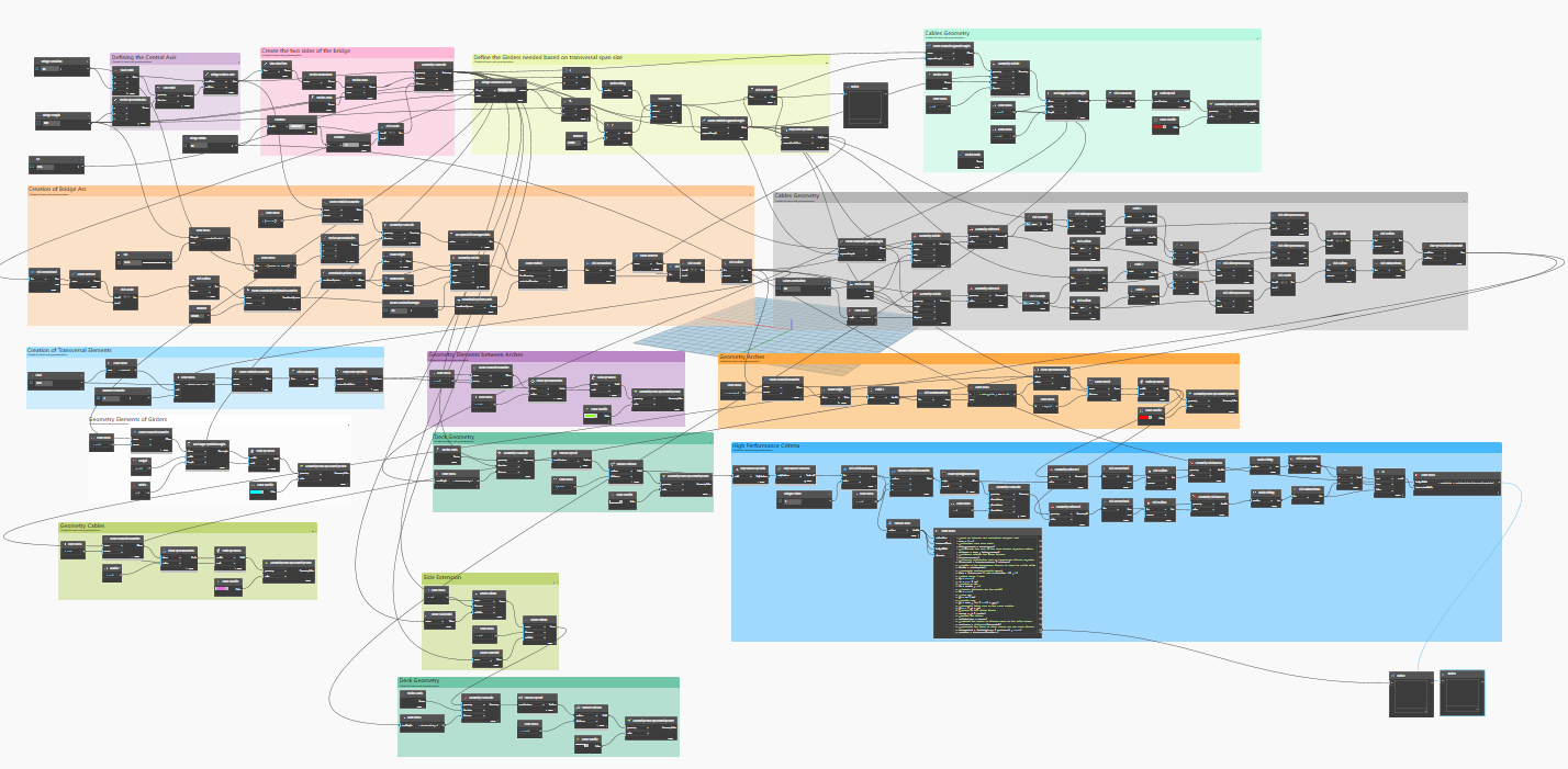
Figure 1. Dynamic Workflow
Results and Discussion
The three design alternatives are shown in the Figure below.
Fig 2 shows a parametric model when L=60 , T/L=0.12 , H/L=0.15 ,Cable inclination=10. The quantity of steel is around 270 tonnes and the lost width is 1m which is optimum.
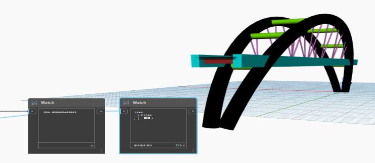
Fig2. Parametric Model Design1
Fig 3 shows a parametric model when L=120 , T/L=0.135 , H/L=0.20,Cable inclination=25. The quantity of steel is around 3800 tonnes and the lost width is 1m which is optimum.

Fig3. Parametric Model Design2
Fig 4 shows a parametric model when L=180 , T/L=0.15 , H/L=0.25,Cable inclination=36. The quantity of steel is around 660 tonnes and the lost width is 1m which is optimum.
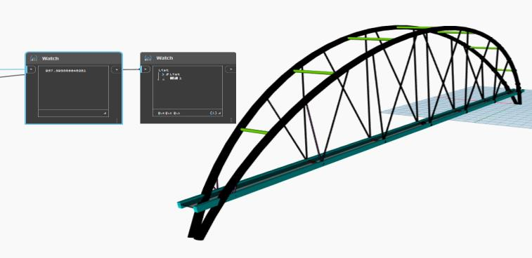
Fig4. Parametric Model Design3
After giving alternate value for the design parameters in order to check the high performance criteria of the bridge, we can conclude that the functionality of the bridge is good at the respective range. But since we implemented only the super structure of the railway bridge, we cannot completely conclude that the this will be the best suitable design option and sub structural elements also will contribute to the structural stability. In addition external factors such as location, soil and influence of external forces (seismic forces) also can be considered.
dyn file :- bridge
References
Sack-et-al., 2003, “Parametric 3d modelling in building construction with examples from precast.”
Pritchard, B., 1994, “ Haunched bridges and the sucker deck principle: Beneficially varying deck depth to match headroom over obstacle crossed.”
Sanpaolesi, L., Croce, P., 2005, “Design of Bridges: guide to basis of bridge design related to Eurocodes supplemented by practical examples.”