1. Introduction
A bridge railing system, also known as a bridge guardrail, is an important safety feature for any bridge, large or small. It serves as a barrier between vehicles and pedestrians, and the water or other hazards below. The purpose of a bridge railing system is to prevent accidents and protect people and vehicles from falling off the bridge.
Bridge railing systems come in a variety of materials, including concrete, metal, and plastic. The choice of material depends on the type of bridge, the local environment, and the traffic volume. Some bridge railing systems are designed to absorb impact in the event of a collision, while others are designed to redirect vehicles away from the edge of the bridge.
In addition to serving as a barrier, bridge railing systems also play a role in the aesthetics of a bridge. They can be designed to blend in with the bridge or to make a statement with their design. Regardless of their appearance, all bridge railing systems must meet strict safety standards to ensure their effectiveness.
Over the years, bridge railing systems have undergone significant advancements in terms of both design and materials. Today, bridge railing systems are stronger, lighter, and more durable than ever before, providing a high level of protection to people and vehicles.
2. Goal and scope
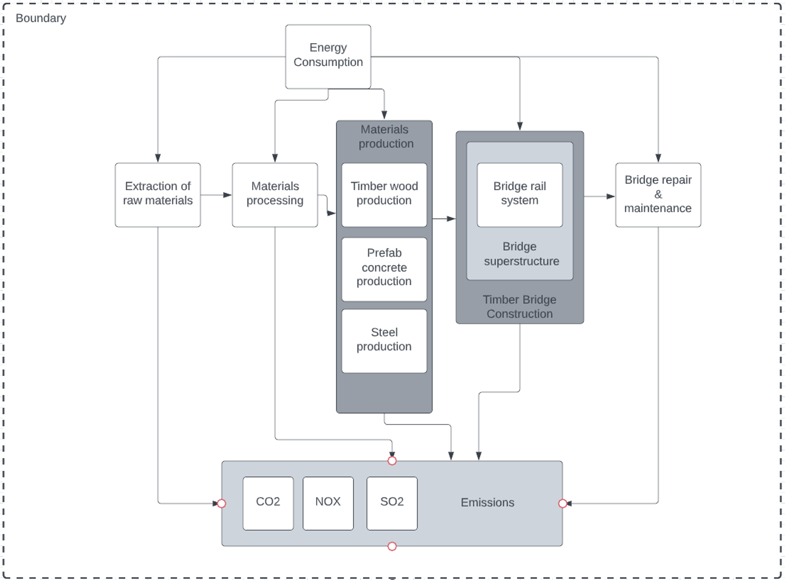
The goal of this assessment is to assess the carbon footprint of the bridge railing system throughout its life cycle. This includes the processing and production of raw materials for the bridge railing system, the production of inputs into bridge rail construction and the maintenance of bridge rail service life, as well as energy consumption and emissions of CO2, NOx and SO2, which are major contributors to the global warming problem. The scope and boundaries of this assessment are shown in Figure 1.
Figure 1
Scope and boundaries of this assessment
3. Design Options
The bridge railing system consists of two main components: posts and rails. This article focuses on the six options consisting of timber, steel and prefab concrete posts and rails of timber and steel. In practical works, the load-bearing capacity and construction methods and maintenance procedures vary from material to material. This affects the decision-making at the beginning of the project. Figure 2 shows a sketch of the bridge railing system. Figure 3 shows cross-sections of the six design alternatives.
Figure 2
Bridge railing system
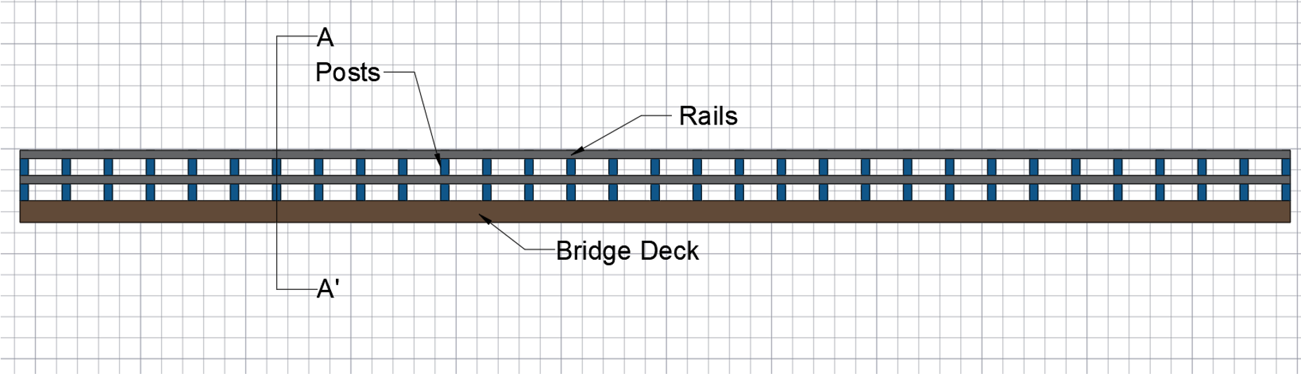
Figure 3
Cross-sections of the six design alternatives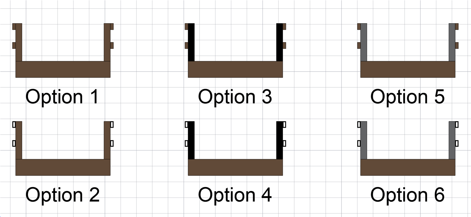
Table 1
Materials of the six design alternatives
| Design option | Posts Material | Rail Material |
| Option 1 | Wood | Wood |
| Option 2 | Wood | Steel |
| Option 3 | Steel | Wood |
| Option 4 | Steel | Steel |
| Option 5 | Prefab concrete | Wood |
| Option 6 | Prefab concrete | Steel |
4. Life-Cycle timeline
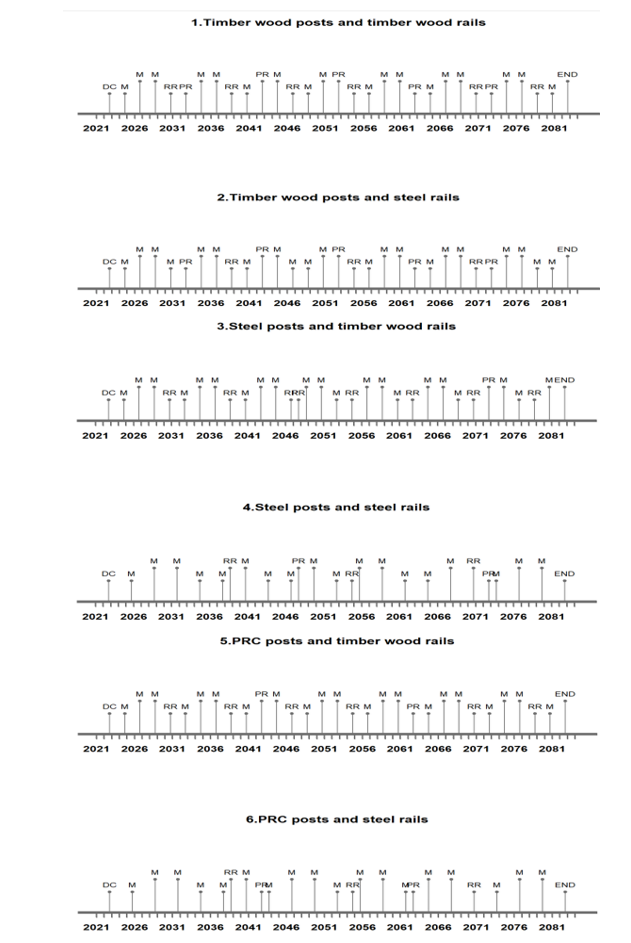
The lifecycle timeline clearly shows the schedule of activities of the bridge railing system during its lifecycle, so that engineers can account for materials for maintenance and replacement of the various design options. This facilitates the subsequent analysis of the LCI. This assessment sets the start date of the bridge railing system on 17 January 2023. The life cycle is 60 years. The maintenance and replacement indicators for each element are entered into the R script to obtain Figure 4. Figure 4 shows the life-cycle timeline of the various design options. The ‘PR’ stands for post replacement and the ‘M’ stands for maintenance of the bridge railing system. The ‘RR’ stands for rails replacement.
Figure 4
Six options for life-cycle timeline
5. Life Cycle Inventory (LCI) and Analysis
The LCI is based on the energy consumption and environmental indicators including CO2, NOX and SO2, together with the dimensions and the maintenance and replacement timeline for each design to analyse the Life Cycle Cost. Figures 5 to 8 show the histograms for the amount of each scenario in terms of energy consumption, CO2, NOx and SO2 emissions. This provides a reliable basis for engineers to make design decisions. The radar diagram Figure 9 shows the proportion of all indicators. These graphs provide a more visual comparison between the various options for each indicator.
Figure 5
Energy consumption
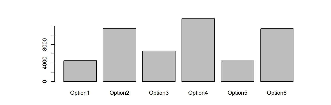
Figure 6
CO2 emissions
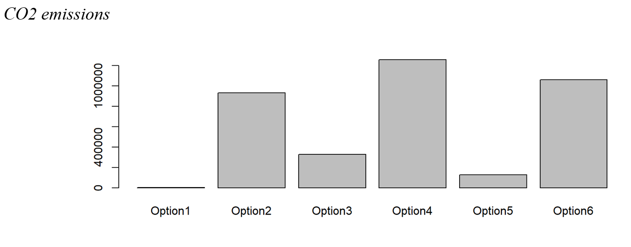
Figure 7
NOx emissions
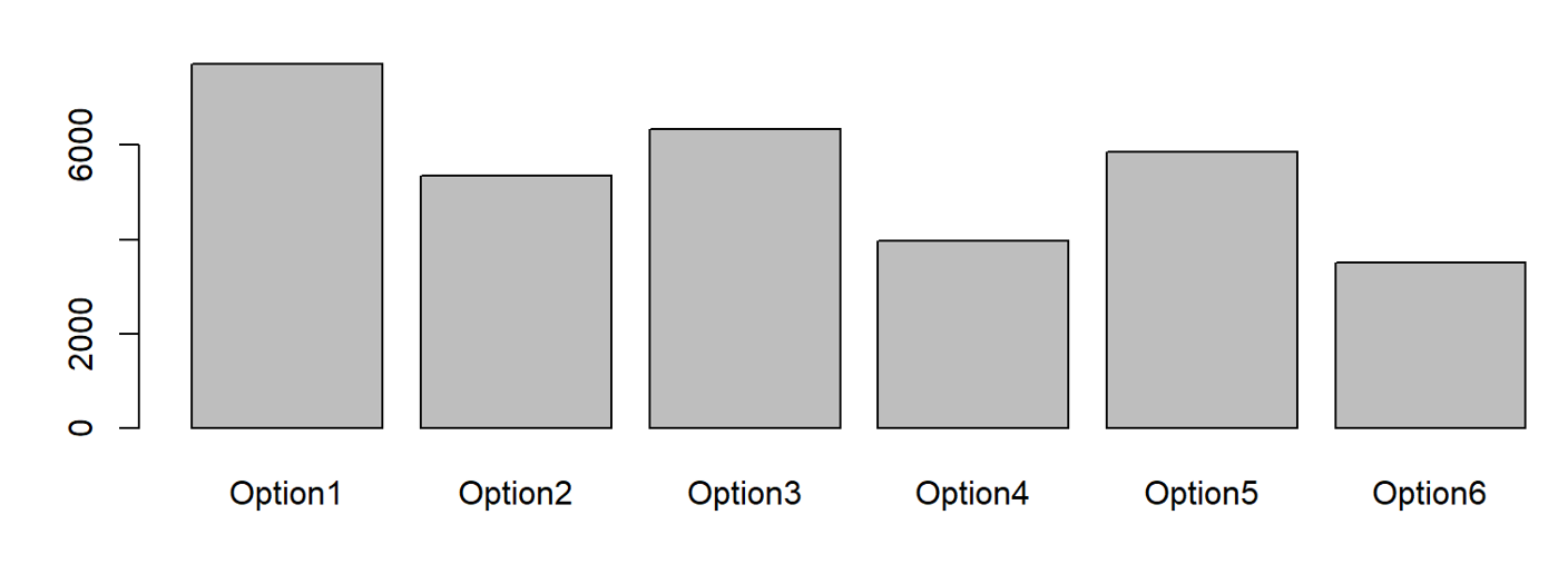
Figure 8
SO2 emissions
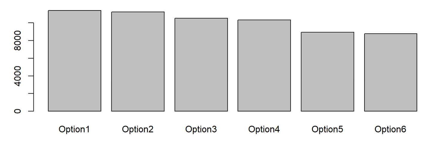
Figure 9
LCI radar diagrams
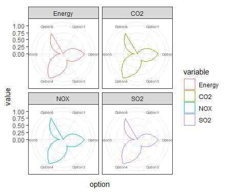
From the above figures, it is clear that option 1 is the best in terms of energy consumption and CO2 emissions. Option 6, on the other hand, has the lowest NOx and SO2 emissions. The multiple indicators make decision-making complex. Therefore the Analytic hierarchy process (AHP) and the Technique for Order of Preference by Similarity to Ideal Solution (TOPSIS) are adopted to perform Multi-criteria decision analysis for the six design options.
6. Multi-criteria decision analysis (MCDA)
6.1 Analytic hierarchy process (AHP)
Vaidya and Kumar mention in their research that AHP is a multiple-criterion decision-making technique that has been utilised in practically all decision-making applications. In terms of application, AHP has most frequently been employed in engineering, personal, and societal categories (2004). In the research from Satty, the scaling rules 1-9 are applied to the options pairwise comparison (1990).
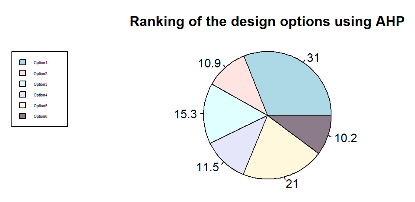
Based on the standard AHP calculation method, we obtain a pie chart Figure 10 in R language. From this chart, we can see that Option 1, wood posts and rails, is the best design option, while Option 6 is the worst. And the best-ranked Option 1, option 3 and option 5 all have wooden materials in the elements.
Figure 10
Ranking of the design options using AHP.
6.2 Technique for Order of Preference by Similarity to Ideal Solution (TOPSIS)
According to the research (Opricovic & Tzeng, 2004), The TOPSIS method is based on the idea that the best choice is the one that is “closest” to the ideal solution and “furthest” from the “negative-ideal” solution. Concerning the use of materials in the bridge railing system in this paper, NOx and SO2 have been dealt with efficiently due to improvements in production processes. Energy use and CO2 emissions are still major problems worldwide.
Figure 11
TOPSIS 1 with minimization criteria
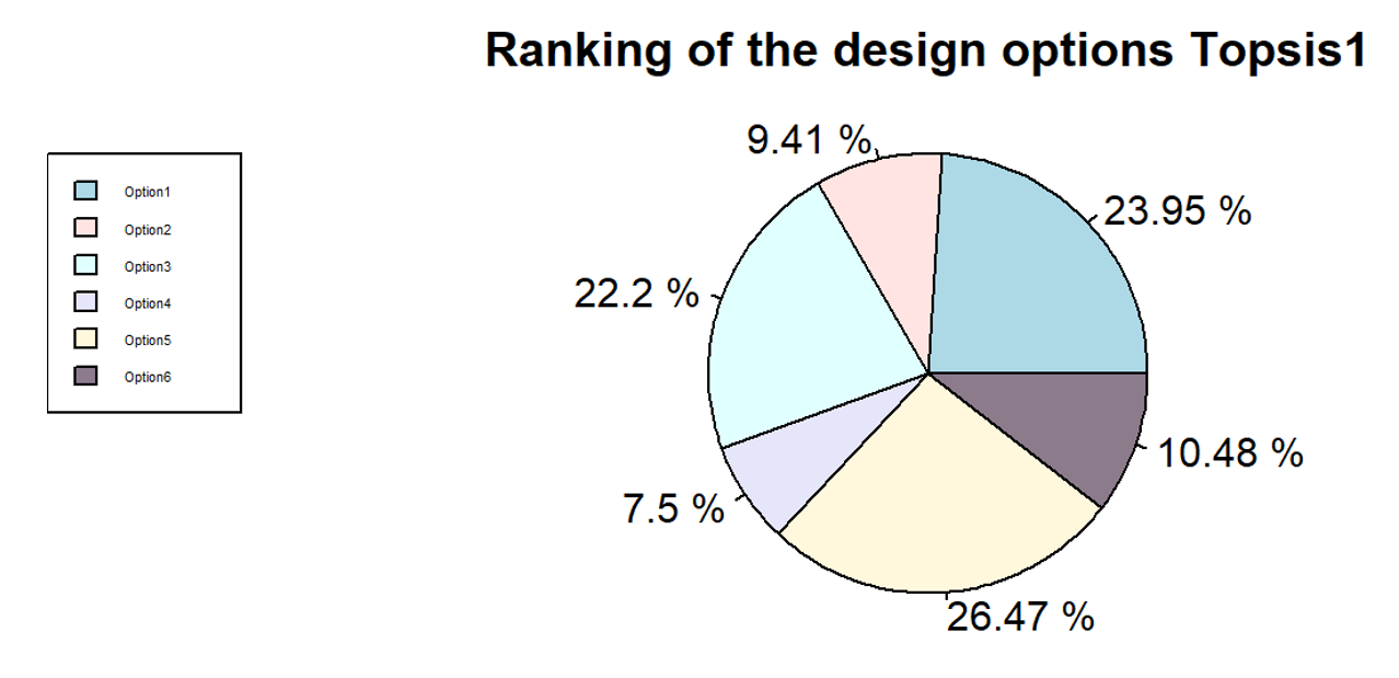
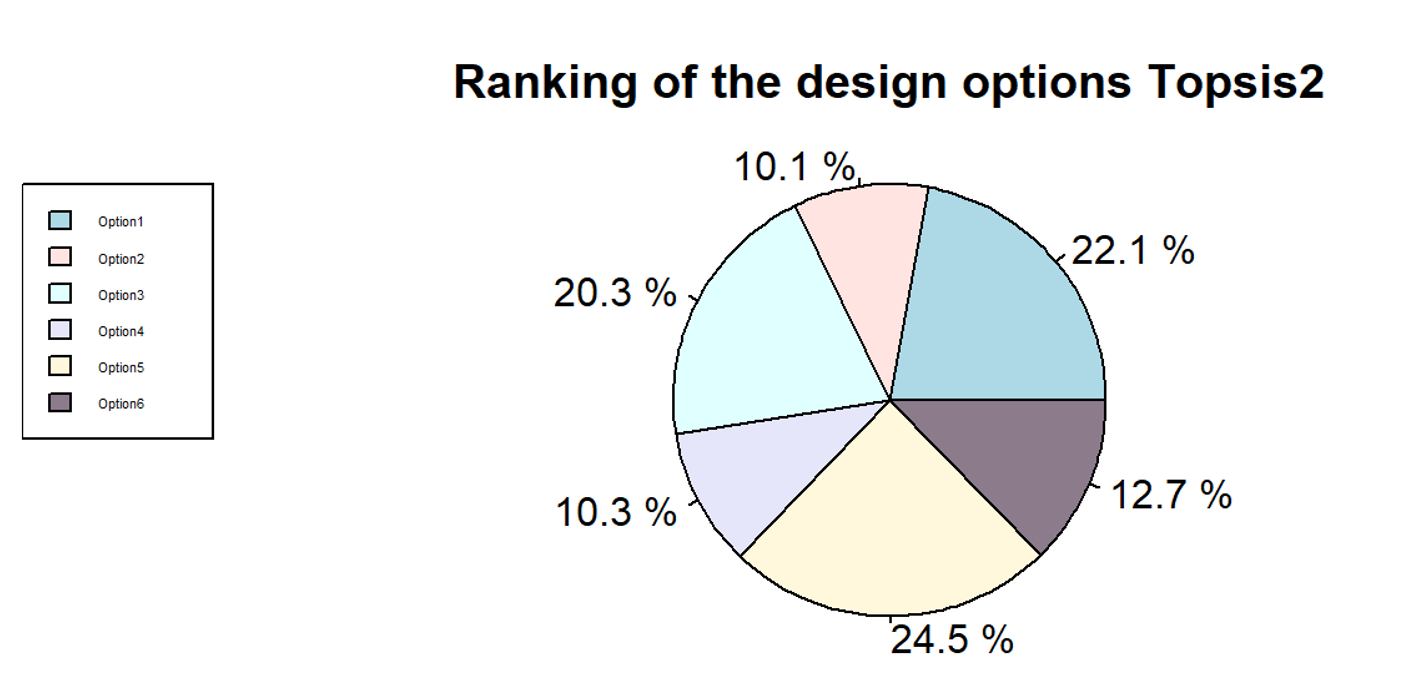
Figure 12
TOPSIS 2 with the positive and negative ideal solution
The two figures above are generally similar. The difference is in the ranking of Option 1 and Option 5. This is because out of the four indicators, Option 1 has a clear advantage over Option 5 only in terms of CO2 emissions.
Comparing AHP, TOPSIS1 and TOPSIS2 results, it is easy to see that the use of wood in the bridge railing system is effective in reducing energy consumption and CO2 emissions, which makes the use of wooden elements rank higher. However, from an engineer’s point of view, precast concrete has better shear strength than wood, which improves the overall safety of the bridge system and requires less replacement during its lifetime. The TOPSIS2 results are therefore more reasonable from an engineer’s point of view.
7. Conclusion
This assignment’s main objective was to develop a multi-criteria decision analysis (MCDM) for six bridge rail design options by applying life cost analysis vitalising pre-existing data and some hypothetical data. The following conclusions can be drawn from the analysis:
Initial of all, it is crucial to emphasise that the LCA study’s first phase is establishing its goals and scope. In general, it is required to initially specify the LCA’s assessment goals before specifying the research object’s functions, functional units, system boundaries, categories of environmental effects, etc.
Secondly, the configuration, size and choice of materials of the system and the maintenance options during its life cycle are important. This can seriously affect the outcome of a system’s life cost analysis. It is therefore essential to ensure the accuracy of the data for each material and quantity of the system.
Lastly, scientific MCDM methods such as AHP and TOPSIS provide an intuitive and scientific basis for engineers to make decisions about system design. In this paper, a life cycle cost analysis and MCDM of the bridge railing system were carried out. The results of TOPSIS 2 with the positive and negative ideal solution are closer to the actual engineering situation. Therefore, Option 5, which includes precast concrete posts and wood rails, was identified as the best design option.
Reference
For Industry. (n.d.). NZTIF. https://www.nztif.co.nz/for-industry
Mild Steel Hollow Section | Square, Rectangular, Circular | Metal SuppliesTM. (2018, August 5). Metal Supplies. https://www.metalsupplies.com/products/mild-steel-hollow-section/
Nisbet, M. A., VanGeem, M. G., Gajda, J., & Marceau, M. L. (1997). Environmental Life Cycle Inventory of Portland Cement Concrete. World Cement, 28(4), 100–103. http://www.nrmca.org/taskforce/Item_2_TalkingPoints/Sustainability/Sustainability/SN2137a.pdf
Opricovic, S., & Tzeng, G. H. (2004). Compromise solution by MCDM methods: A comparative analysis of VIKOR and TOPSIS. European Journal of Operational Research, 156(2), 445–455. https://doi.org/10.1016/s0377-2217(03)00020-1
Puettmann, M. E., & Wilson, J. B. (2005). LIFE-CYCLE ANALYSIS OF WOOD PRODUCTS: CRADLE-TO-GATE LCI OF RESIDENTIAL WOOD BUILDING MATERIALS. Wood and Fiber Science, 37, 18–29. http://www.corrim.org/pubs/reports/2005/swst/18.pdf
Rebizer, G., Ekvall, T., Frischknecht, R., Hunkeler, D., Norris, G., Rydberg, T., … & Pennington, D. W. (2004). Life Cycle Assessment Part 1: Framework, Goal & Scope Definition, Inventory Analysis, and Applications. Environment International, 30(5), 701-720.
Saaty, T. L. (1990). An Exposition of the AHP in Reply to the Paper “Remarks on the Analytic Hierarchy Process.” Management Science, 36(3), 259–268. https://doi.org/10.1287/mnsc.36.3.259
Vaidya, O. S., & Kumar, S. (2006). Analytic hierarchy process: An overview of applications. European Journal of Operational Research, 169(1), 1–29. https://doi.org/10.1016/j.ejor.2004.04.028
Back to: Integration Context of the Civil Systems