1. Introduction
In the dynamic landscape of modern transportation infrastructure, the selection of a railway bridge design holds profound implications for sustainability and efficiency. This report delves into the intricate realms of life cycle analysis and multi-criteria decision-making, with a specific focus on three distinct design alternatives. These alternatives involve prefabricated concrete girders with cast-in-place decks, steel girders with prefab concrete decks, and steel girders with fiber-reinforced polymer decks. Central to our exploration is the railway ballast—a critical component influencing track stability and, consequently, the overall performance of the bridge. (The references are given in the Full Report at the end of the page.)
2. Goal and Scope
The goal of this assessment is to conduct a comprehensive life cycle analysis and multi-criteria decision-making process for three railway bridge design options, each incorporating different materials and methodologies for the rail ballast. The primary objective is to evaluate the environmental, economic, and durability implications associated with the use of prefabricated concrete girders with cast-in-place decks, steel girders with prefab concrete decks, and steel girders with fiber-reinforced polymer decks, specifically focusing on the type of ballast employed in each case.
The scope encompasses the entire life cycle, including the construction, operational, and maintenance phases. By scrutinizing the intricate interplay of design choices and ballast materials, this assessment aims to provide valuable insights for informed decision making, contributing to the development of sustainable and resilient railway infrastructure.
3. Design Options
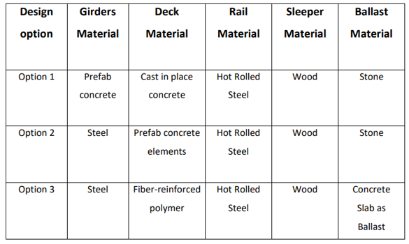
The proposed railway bridge design options encompass three distinct alternatives. The first entails prefabricated concrete girders supporting a cast-in-place deck, accompanied by a conventional railway structure incorporating rails, wooden sleepers, and stone ballast. The second design features steel girders supporting a prefabricated concrete deck, with a similar railway configuration. The third alternative introduces innovation with steel girders and a fiber reinforced polymer deck, coupled with a railway track comprising rails, wooden sleepers, and a concrete slab as ballast. These design variations present diverse approaches to structural composition and material utilization, emphasizing the critical role of the chosen ballast material in track stability and, consequently, overall bridge performance.
4. Life Cycle Inventory
The following table presents the composition of different materials used. For each material, we collected information about energy consumption for fabrication and processing (MJ/t), CO2, NOX, SO2 (kg/m3) and cost associated with extraction, processing, manufacture, and construction.
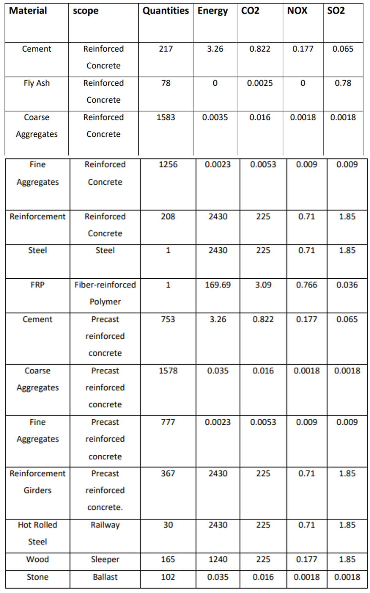
The “quantities” column has a different meaning, depending on the materials. For Reinforced Concrete and Precast reinforced concrete those are the quantities of materials consumed to produce a cubic meter of concrete, respectively the reinforcement in Kg usually used for 1cubic meter of concrete. For steel and Fiber-reinforced Polymer is indicated 1, because the energy consumed as well as the emissions are indicated for each Kg of materials produced and consumed. For Hot Rolled Steel and wooden sleeper which is used as rail track has the total quantity required for the bridge. The stone is calculated in cubic meter.
5. Life Cycle Timeline
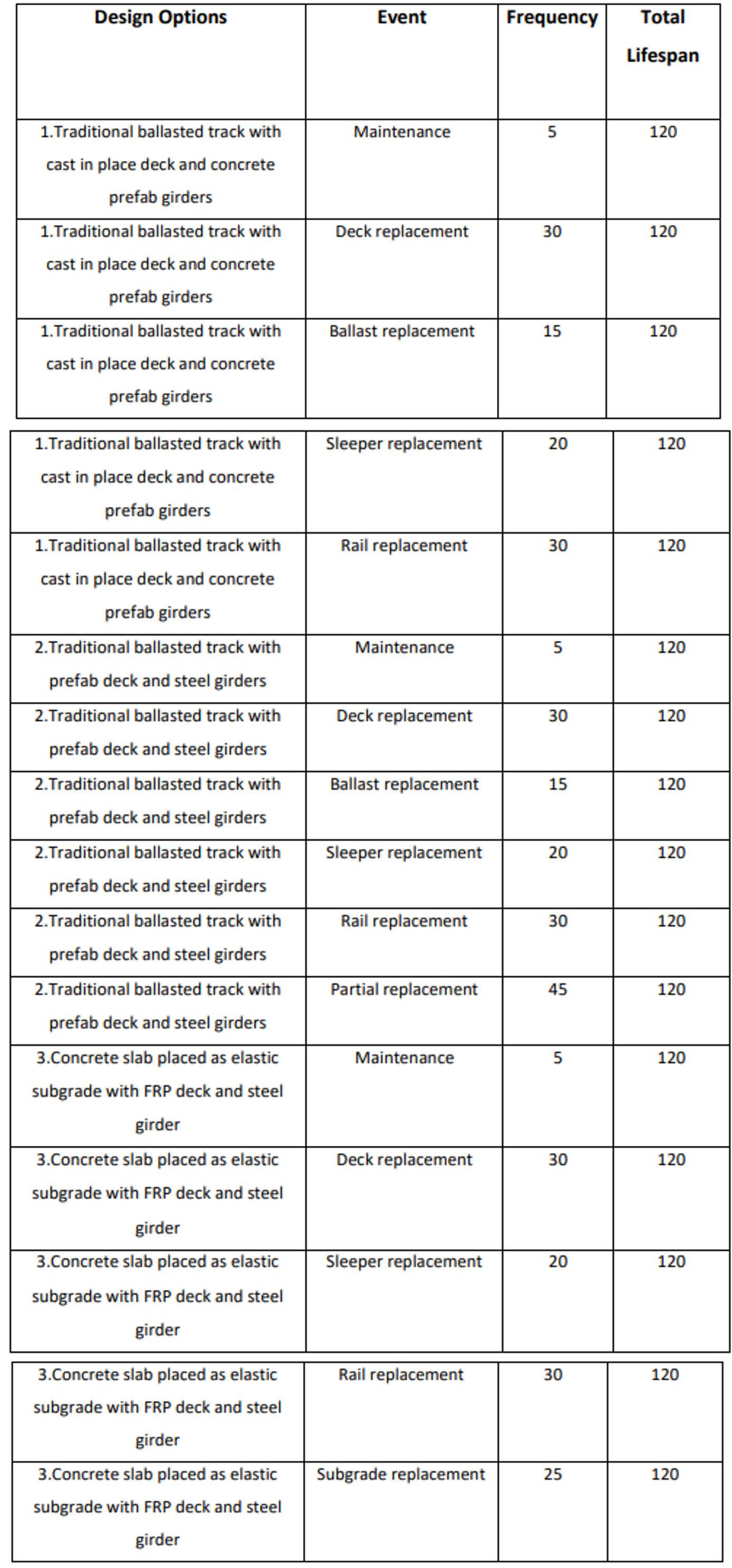
The lifespan of typical Railway Bridge is around 120 years. During this lifetime, there are several maintenance and repair events that the total system may need to undergo. For the three design options there are some frequent interventions and some replacement activities take place. The interventions are summarized in the following table:
6. Life Cycle Analysis
The results of the Life Cycle Inventory Analysis were computed using R, which facilitated the determination of material quantities for each design options and the total material needed for every design option. Subsequently, the environmental indicators were applied to calculate the corresponding environmental impacts for each option. The findings are presented in the following bar plots.
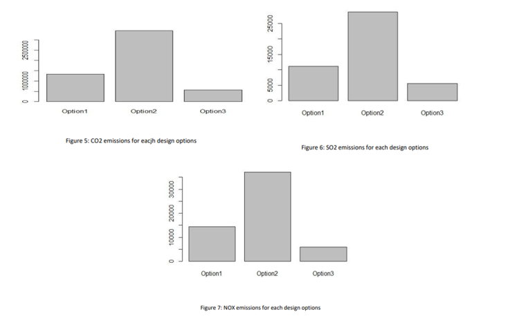
The environmental indicator that exhibits the most variation among the three design options is carbon emissions. Option 3 has the lowest, possibly influenced by the bio-chemical behavior of concrete slab replacing the stone over its lifetime and the very less amount of repair required. Similarly, Option 3 shows the lowest SO2 and NOX emissions.
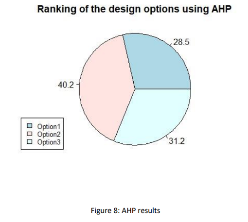
7. MCDM – Analytic hierarchy process (AHP)
In the previous section we analyzed the values for each of the environmental indicators independently. This is while in reality we need to see and analyze the effects of all the influential effects together to be able to make informed decisions. To achieve this, in the final section, we establish the analytic hierarchy process (AHP) to see the integrated effect of all our multi criteria based on their importance. Figure 8, represents the result of the multi criteria decision making process. It can be clearly seen that option number 2 which has the highest score with nearly 41%, followed by the other design option with 31.2 %. Option 1 has the lowest score standing less than 29. It seems that option 1 and 3 are very close.
Downloadable Content
Full Report: Md Rakib Bin Kayesh
| Main Page | Introduction | Integration Context of the Civil Systems | Maintenance Strategies | Life Cycle Analysis | Multi-Objective Optimization |