Introduction
The bridge is a vital infrastructure facility for the long-term growth of the social and economic events of a country, city, or area. It can provide commodities and services essential to enable, sustain, or enhance societal living conditions. Structural steel has been the organic solution for long span bridges since 1890, when the Firth of Forth cantilever bridge, the world’s major steel bridge at that time was completed. Bridges generally outlive their designers and provide a visual testimonial to the skill and ingenuity of their engineers and builders. Steel is a versatile and effective material that provides efficient and sustainable solutions for bridge construction, particularly for long span bridges or bridges requiring enhanced seismic performance [1]. Normal building steel has compressive and tensile strengths of 370 N/sq mm, about ten times the compressive strength of a medium concrete and a hundred times its tensile strength [2]. A special merit of steel is its ductility due to which it deforms considerably before it breaks, because it begins to yield above a certain stress level. Designing a steel bridge can be considered after establishing the foremost uses of the bridge as well as the interfaces with the environment and the other systems around us like in a tramway infrastructure as an important network element.
Ontology Model
The .owl file for the ontology can be found here.
The ontology comprises the following answers to the questions,
- Purpose: The purpose of this ontology is built to denote the structural concepts for a steel bridge design.
- Scope: The ontology contains the conceptual design relevant to its components of substructure & superstructure, different types of steel materials and the numerous uses of the bridge.
- Intended End-Users: The intended end users are the modeler and the engineers involved in design of steel bridge.
- Intended Uses: The intended use of this ontology is to represent the structural concept in the model to use it for further research and analysis. Moreover, additional information can be added to this ontology and can be developed with vast details as it has been kept with basic concept of designing a steel bridge.
Accordingly, from my background research, I have developed the ontology following the suggestions Noy, and McGuinness made in chapter 4 of our reading task and the provided bridge-example where the physical and functional components were acknowledged, and the ontological model is divided into the classes. It could be more elaborated on the basis of different types and its use and sub classes.
The Ontological model for steel bridge is shown as below and at the following link.
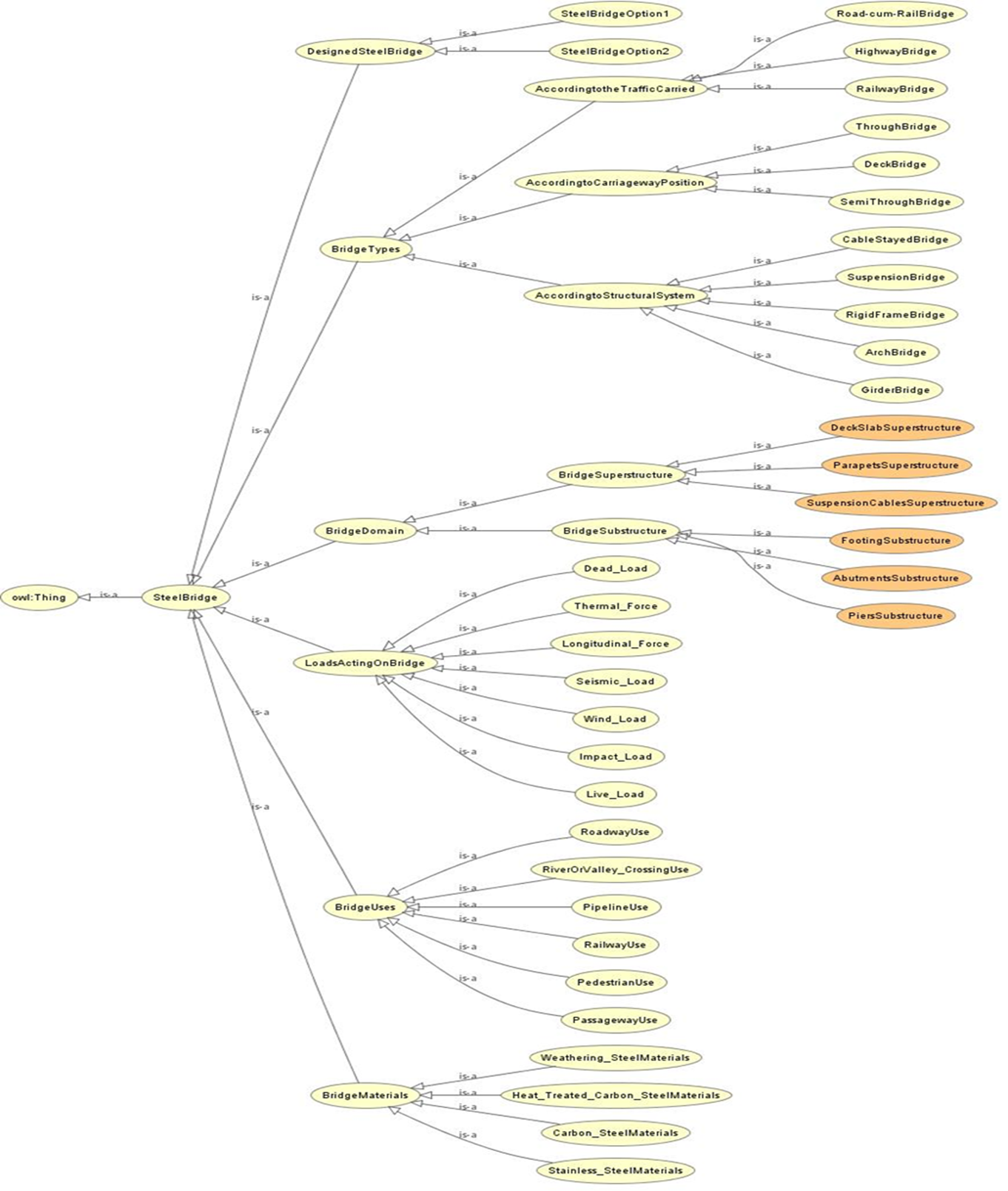
Figure1 Ontological Modeling for Steel Bridge
Parametric Model
The .dyn file for the parametric model can be found here.
Bouguessa et al. [3] deliver clarifications based on the essential features of BIM and hypothesize that a model should contain the notions of 3D geometry, parametric objects, and information. Its principal objective is to offer a simulated representation of a structure, which can be understood by a consumer, but also to give adequate information to define the constituent components of the represented entity.
The steel arch bridge is divided into segments for bracing and kept the value in mid-range (20-30) as too much gap into the bracing can cause failure in truss structure and more congestion of the bracing can raise the self-weight of the bridge which is economically not contented. Top and bottom chords as well as the horizontal bracings for both elevation of the bridge are kept identical for the unique appearance.
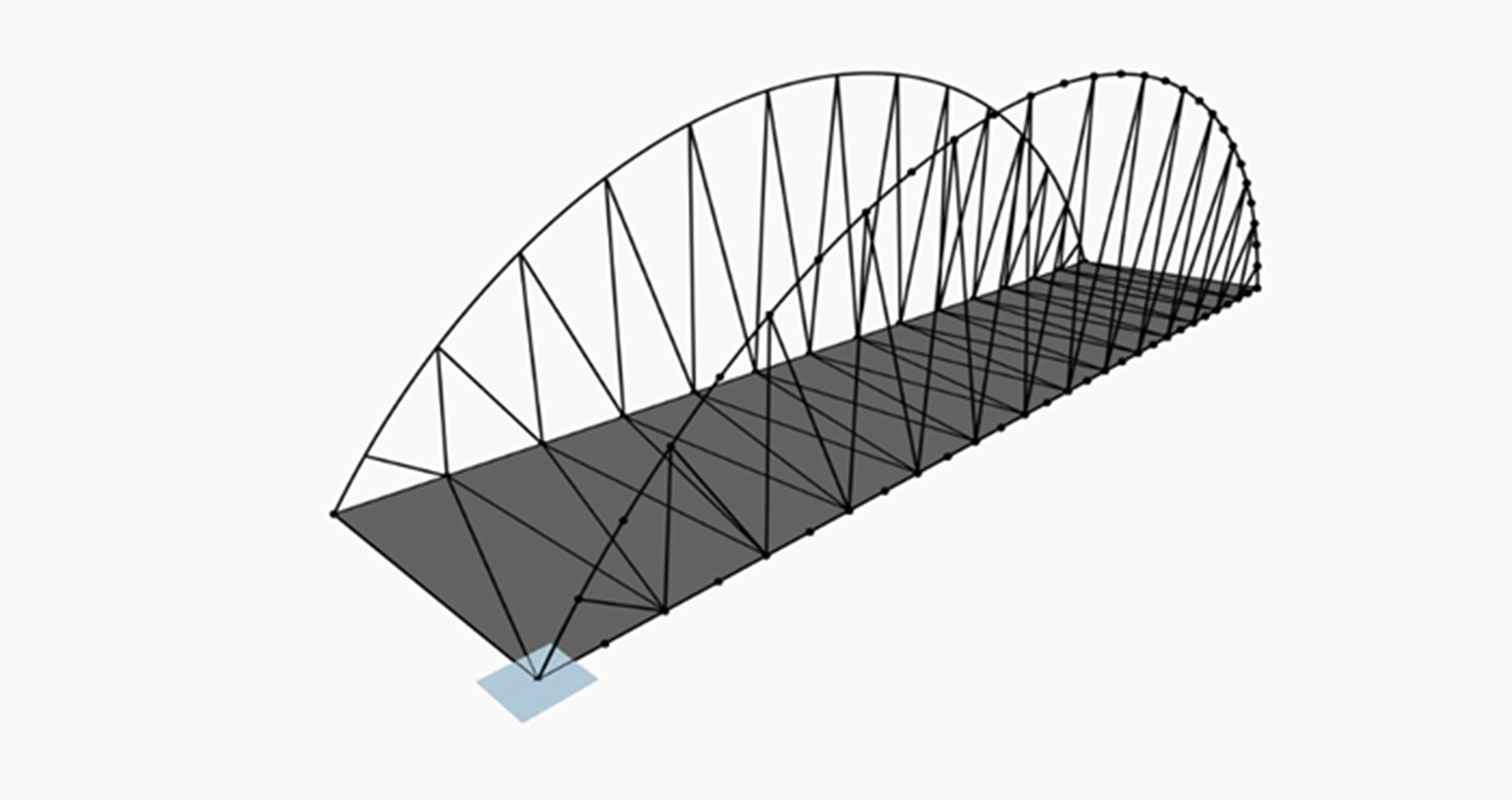
Figure 2 Steel Arch Bridge Model Geometry
Components are the vital elements to carry the loads of bridge. According to the design criteria, these components can be variable to their sizes, shapes, and properties. Here, two different design options have been taken for the steel bridge with the variation of the component’s properties.
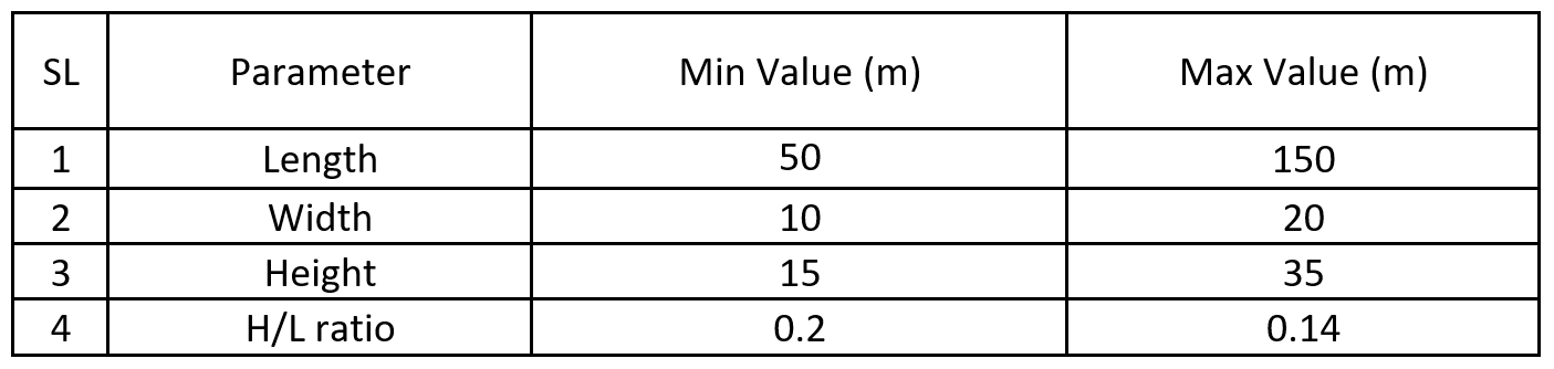
Table 1 The Steel Bridge Design Parameter Options- Minimum & Maximum Values
The Dynamo nodes is used to perform iterations that consists of a basic programing understanding, using a simple set of rules in order to allow the parametrization to take place. As shown in the below figure 3.3, “Code-block” was created to define the interval of the allowed changes to be made.
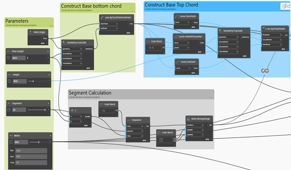
Figure 3 Dynamo Nodes
The rules of the loop are carefully noticed in Figure 3.4. Dynamo will use the defined variables using a simple loop equation to satisfy the loop.
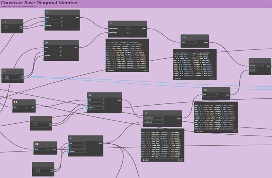
Figure 4 Dynamo nodes in depth
The increasing length for the bridge can cause buckling or sagging due to its dead load and live load. Moreover, the higher length with congested width may not be resistant to the vertical and horizontal wind force. On the other hand, width may not affect the load resistance criteria of bridge but can be saggy and create bottleneck for the traffic in pick time. The amplitude of critical buckling load is largely influenced by geometric and mechanical properties of the wind bracing system, which is commonly arranged by using Vierendeel, X-shaped, and K-shaped configurations. By parametrization of all three parameters, H/L ratio and L/W ratio needs to be defined precisely and broadly. While our file is accurate and fast, it must be borne in mind that it cannot yet be used for geometries with detail levels that are too high. Indeed, the method used to build the cross-section is accurate and offers a very large choice of geometric possibilities but does not allow to create some details of very small dimensions. The world of digitalizing is wide and offers many new topics for parametric studies, and there are several of the suggestions we could possibly try to further extend the knowledge about parameterization in a BIM early stage designing.
References
[1] Steel Bridges, Weiwei Lin, Teruhiko Yoda, in Bridge Engineering, 2017.
[2] Steel bridge structure – advantages, elements, and components By Constro Facilitator.
[3] A. Bouguessa, D. Forgues, S. Dor´e, La compl´ementarit´e entre le Building Information Modeling (BIM) et le Product LifeCycle Management (PLM) en passant par le Lean Construction (LC), Congr`es g´en´eral 2013 de la SCGC, 2013.