Ontological Modeling
Introduction
Transportation systems are an essential component of any modern ecosystem and human society. Tunnels have various functions such as transportation, water conveyance, mining, and utility infrastructure. Constructing durable tunnels is crucial for expanding cities and growing infrastructure. Sustainable tunnel construction starts with careful planning and accurate product modeling. The Sequential Excavation Method, also known as the New Austrian Tunneling Method (NATM), was developed in the mid-1900s. This method was initially created to support tunneling sites with weak ground where the soil masses surrounding the tunnel are over-stressed and require an additional support system. The NATM offers flexibility in geometry such that it can accommodate almost any size of opening.
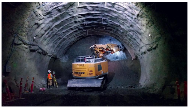
Figure 1: NATM Construction Method
Purpose and Scope
Conceptual tunnel design requires a well-structured ontology to represent essential concepts and relationships for modeling tunnel engineering, specifically regarding structural design. Effective collaboration and communication among structural engineers, construction teams, and management personnel involved in the project are facilitated by a well-designed ontology. An ontology provides a formalized framework for tunnel design, construction, and maintenance, which ensures efficient collaboration during the construction process and lays the groundwork for future modeling, particularly in the context of Building Information Modeling (BIM).
This ontology introduces tunnel physical components, materials, and uses. It details the fundamental elements of a tunnel, such as lining, reinforcement, shotcrete, and rock bolts. The ontology categorizes potential construction materials and establishes relationships between physical components and tunnel functions.
The intended users of this ontology are structural engineers, and stakeholders, based on the intended use, the future authorities involved.
In computer science ontology is defined as “explicit formal specifications of the terms in the domain and the relations among them”2 . Therefore, this ontology appears to serve as a means of sharing domain knowledge and creating a fundamental conceptual design for the structural design of a NATM tunnel. Having an ontology model of a structure helps all the involved personal to have a better understanding of the structure and materials.
Developing an Ontology
Every tunnel consists of standard components that make up its final structure and support system, depending on the construction method used. The specifications of these components are determined by the design loads, which vary depending on the ground in which the tunnel is being built, whether it be in rock or soil. In the NATM tunnel framework, the ground is considered as the support structure. This implies that the components of the NATM tunnel can be used as basic elements in various types of tunnels. Therefore, the NATM tunnel components provide benefits for generalization across other tunnel types from a product perspective3 . Therefore, as stated by Noy et al., 2002, the NATM tunnel ontology can be used as a general ontology for tunnel structures, as modeled below:
⚫ Physical Components
- Main structure
- Concrete Final Lining
- Primary Member Lining (Concrete)
- Secondary Member Lining (Reinforcement)
- Support Structure
- Rock Bolt
- Shotcrete
- Concrete Final Lining
The two main subcategories of the tunnel are modeled. For the designed options the support structure is considered the same and changes are seen in the main structure.
⚫ Main Material
- Cast-in-place concrete
- Steel
- Waterproofing Membrane
In tunnel engineering, other types of concrete are used such as precast but for NATM the concrete is sprayed therefore the concrete is cast in place.
⚫ Uses
- Subway
- Road
- Sewage
Tunnel Options
The main classes and sub-classes parameters were defined from the literature. There are two design options introduced to provide basic knowledge for the initial design of the tunnel and not as a complete design tool. Therefore only the main structure specifications of the tunnel are considered as a changing value. The tunnel option 1 is a NATM Rail Tunnel outside Salzburg in Austria and option 2 is Bolu Tunnel located on the Istanbul Ankara highway.
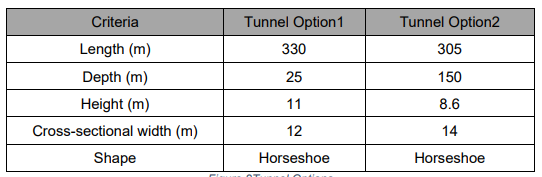
figure 2 : Tunnel Options
In tunnel construction, the depth of the tunnel and the soil or rock characteristics play a crucial role in designing the final lining. Both of our design options have the same physical components but with different values that are taken from the literature. These values can be used as input for the parametric design of an engineer who is using this ontology.
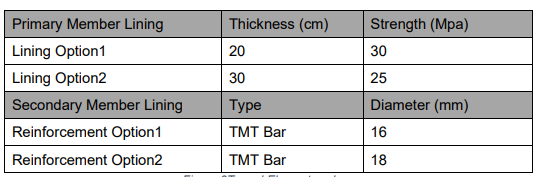
figure 3 : Tunnel Elements values
Visualization of Ontological Modeling
For the developed ontology OntoGraf was created by Protégé displayed in the figure below:
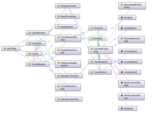
figure 4 : OntoGraf- NATM Tunnel Design
Parametric Modeling
Introduction
The project involves creating a parametric model for a NATM Tunnel after defining its components and building the ontological model in the first assignment. Parametric modeling establishes relationships between design elements, which makes modifications easy and fast. It also improves accuracy, consistency, and collaboration, making it an invaluable tool in design. While creating the model, two different high performance criteria were introduced for the design to assess the overall performance of the model, and three different design options were developed to examine these criteria.
Chosen System
The system chosen, as in the first assignment, is the New Austrian Tunneling Method (NATM). NATM tunnels can be used for various purposes such as roads, sewage, and subways. The geometrical characteristics of the tunnel are subject to change based on its usage. Tunnels are massive constructions that require a significant amount of resources, time, and funding. Therefore, tunnels should be designed to last at least 150 years, considering high-performance criteria ensure sustainability and durability.
Design Challenge
of the Chosen System Tunnels are structural systems that are unique in that they rely on interaction with the ground around them to maintain stability and carry loads. If the support provided by the surrounding ground is lost, the lining can fail. As load is applied to one part of the lining, it begins to deform and creates passive pressure along other parts of the lining. This passive pressure is crucial in preventing the lining from collapsing or buckling1 . The design challenge is, while meeting the client’s geometrical requirements, to design a tunnel lining that balances these forces and is cost-efficient and sustainable.
High-Performance Criteria
Cost
Various factors contribute to the expenses of constructing underground structures. These factors can be broadly classified into three categories: physical, economic, and political. Physical costs are mainly associated with the construction site of the tunnel, such as groundwater control. The location of the tunnel, whether it’s in a rural or urban area, can also bring limitations. The expenses resulting from these limitations are classified as political costs. However, for this project, we will only focus on the economic cost. The primary expenses associated with tunnel construction are the labor, materials, and equipment required2 . In this project, the focus will be on the cost of materials, which is the second most significant cost component, especially concrete which has the largest proportion of the used material.
Environmental Impact
Tunnels are often considered Eco-friendly constructions as they help to reduce potential environmental issues such as traffic congestion, pedestrian movement, air quality, and noise pollution. There will inevitably be short-term environmental impacts during the construction process 3 . In this project, the environmental impact considered is the total global warming potential. The amount of carbon dioxide induced is taken from the Ökobaudat for C25/30 concrete in three stages production, transportation, and installation .
Engineering Rationale
The tunnel is made of reinforced concrete. When evaluating the system, only the main structure is modeled. While the main structure does contain rebars, the influence of the steel on the calculation of high-performance criteria is not considered. This is because the amount of concrete is the deciding factor, not the amount of steel. There is no limit to the length and depth of a tunnel. However, for the purpose of this model and to evaluate the effect of design parameters on performance criteria, we consider the length and depth as constants. To analyze the impact of the tunnel’s geometrical characteristics, we keep the lining thickness constant and vary only the height and width of the tunnel as variables in different design options. Based on the design options table, increasing the height of the tunnel results in higher costs and GWP compared to increasing the width. The purpose of using parametric modeling in designing tunnels is to assist engineers in the initial stages of the project. This method allows them to make modifications to the design according to the client’s requirements and understand how the physical attributes of the tunnel can impact the cost and environment.
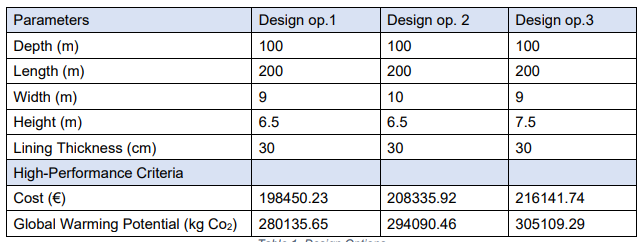
figure 5 : Design Options
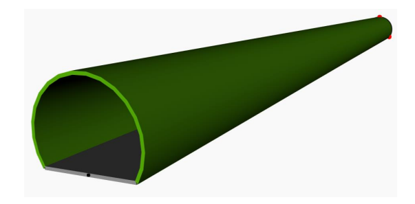
figure 6 : Tunnel modeled with Dynamo
References
- Hung, C., Wisniewski, J., Monsees, J. E., & Munfah, N. (2009). Technical Manual for Design and Construction of Road Tunnels – Civil Elements. U.S. Department of Transportation Federal Highway Administration. https://rosap.ntl.bts.gov/view/dot/50019
- J. Soulis, V. (2016). Numerical Investigation of the In-situ Restoration and Strengthening Schemes of a Damaged Drainage Tunnel. Journal of Civil Engineering Research 2016. https://doi.org/10.5923/j.jce.20160606.01
- Aygar, E. B. (2020). Evaluation of new Austrian tunnelling method applied to Bolu tunnel’s weak rocks. Journal of Rock Mechanics and Geotechnical Engineering, 12(3), 541– 556. https://doi.org/10.1016/j.jrmge.2019.12.011
- Canopied portals for NATM rail tunnel | Dr. Sauer & Partners. (n.d.). http://projects.drsauer.com/technical-info/940
- DESIGN RECOMMENDATIONS FOR CONCRETE TUNNEL LININGS: Vol. VOLUME II: SUMMARY OF RESEARCH AND PROPOSED RECOMMENDATIONS. (1983). Urban Mass Transportation Administration Office of Technical Assistance & Safety, 400 7th Street, SW Washington, DC United States 20590.
- Lee, S. H., Park, S. I., & Park, J. (2015). Development of an IFC-based data schema for the design information representation of the NATM tunnel. KSCE Journal of Civil Engineering, 20(6), 2112–2123. https://doi.org/10.1007/s12205-015-0123-8
- Steel Wire Mesh For Tunnel Support, Reinforcing Mesh. (n.d.). https://www.reinforcedsteelmesh.com/reinforcement-mesh-classified-by-application/steel-wire-mesh-for-tunnelsupport.html#:~:text=We%20always%20adjust%20150mm%20x,is%20not%20less%20than%2020mm.
- Liu, H., Lu, M., & Al‐Hussein, M. (2016). Ontology-based semantic approach for construction-oriented quantity take-off from BIM models in the light-frame building industry. Advanced Engineering Informatics, 30(2), 190–207. https://doi.org/10.1016/j.aei.2016.03.001.
- OEKOBAU.DAT. (n.d.). https://oekobaudat.de/OEKOBAU.DAT/datasetdetail/process.xhtml?lang=en&uuid=24484f95- db48-4d40-9b06-c08ab7b4cd51&version=00.01.002.
- Technical Manual for design and construction of Road tunnels–Civil Elements. (2010). AASHTO.
- “Bridge Tutorial- Parametric model generation with Dynamo”. In: (2020).
<Previous Page Main Page| Individual System|Integrated Systems|Download next page>