1. Introduction
With the rising need for faster surface transport, diverting roads away from rough terrain is no longer an option. This is where the need for Viaducts comes in.
2. Ontological Model
The ontological model is developed to represent the conceptual design of Viaducts with respect to different structural components, possible materials, the sequence of construction, stakeholder scope, and their relations. The intended end-users are the viaduct design, planning and billing engineers.
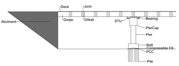
Figure 1: Viaduct – Structural Components (geometric)
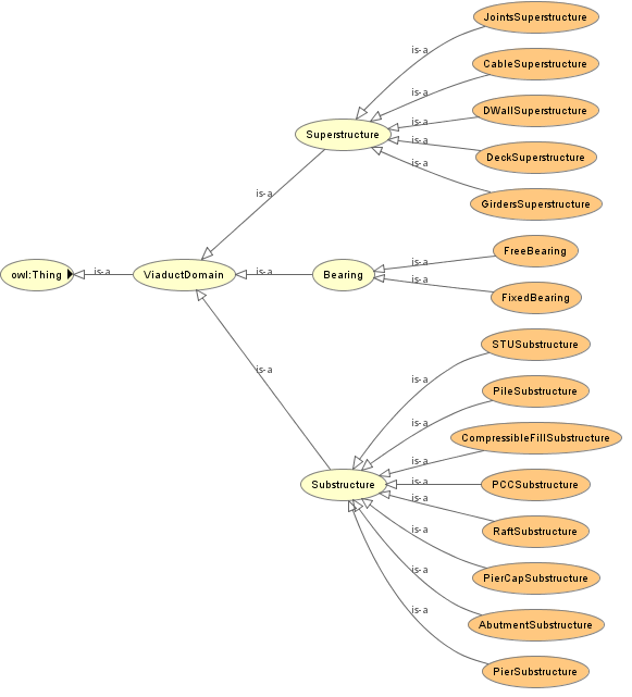
Figure 2: Viaduct – Structural Components (ontological)
The above figures 1 and 2 show the geometric and ontological representation of Viaduct structural components.
We also generate the construction sequence by establishing relationships. The graph generated shows the possibilities where the construction process can be performed parallelly:
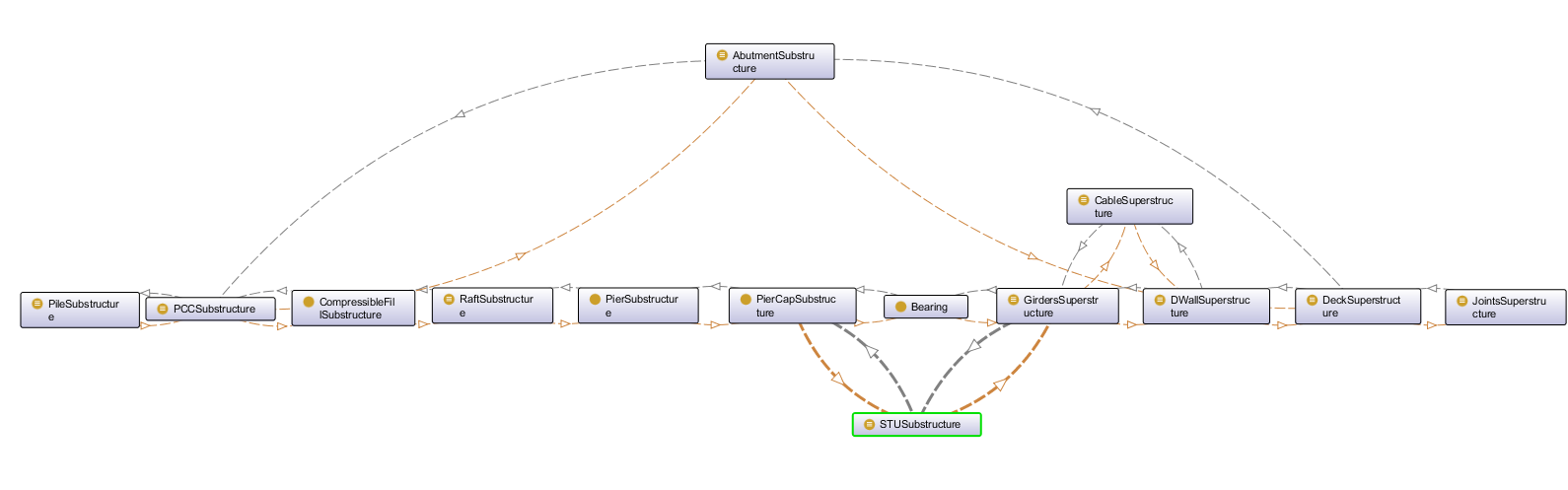
Figure 3: Viaduct-Construction Sequence
We also use the ontological model to define the stakeholder scope and relations, as shown in the figure below:
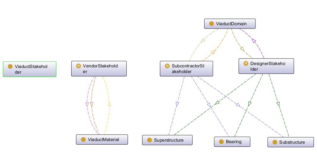
Figure 4: Viaduct-Strategies
The following link provides you with the .owl file:

3. Parametric Model
The main constraint of the model is the location of the bridge being in a river valley.
The following diagram illustrates the effect of this geometry on the model and the interdependencies within the system. This geometry is also implemented in the integrated model.
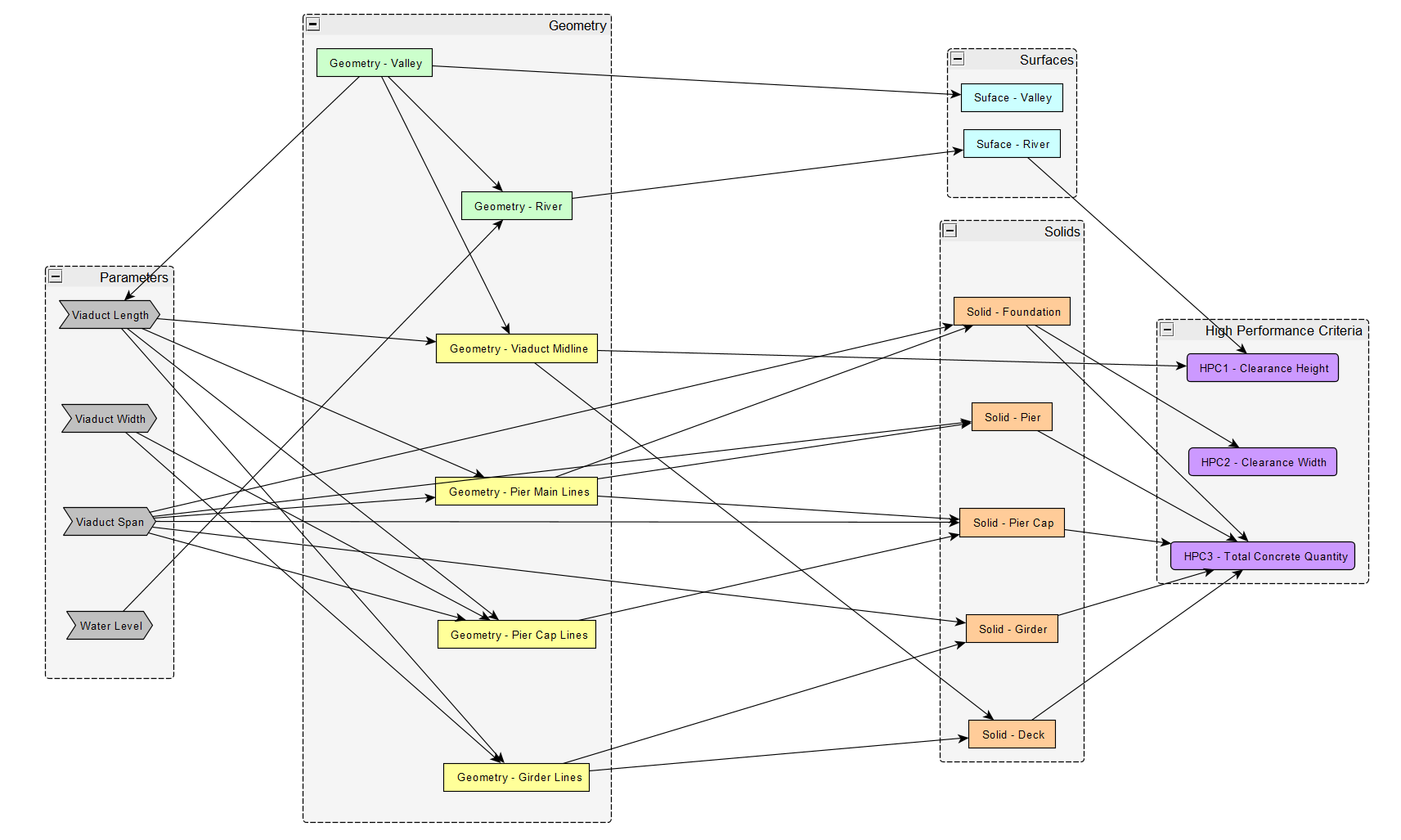
Figure 5: Viaduct-Geometric constraints and system interdependencies
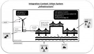
The main objective of the design is to model a viaduct having minimum length i.e. minimum height and optimal span while ensuring both vertical and horizontal clearance[] respectively for the ship movement, with an aim of reducing total quantity. The objective of ship movement can be resolved by implementing the idea of a vertical lift bridge and this resolution is further discussed in the integration context.
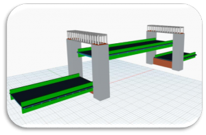
Here, you can see the visualization of the parametric model:
The following link provides you with the .dyn file:
go to
Reference:
[1] Guide Clearances, 33 CFR Chapter 1, Subchapter J – Bridges, United States Coast Guard, U.S. Department of
Homeland Security