Integration Context
The integration context of the selected system works via the following three principals
- Integration of relative positions of the individual structures
- Integration of the relative sizes of the structures
- Integration of all the system’s sizes with a single parameter namely Percentage Population.
Figure 1 shows the complete integrated code for the infrastructure system which integrates all four structures, i.e. Frame Structure, Tiny House, RCC Bridge, and the Retaining Walls in the 3D Space.
The systems are connected to model a real-life scenario where a bridge connects the RCC Building a tiny house which is separated by a valley. The bridge has retaining walls on either end to support the soil and foundations of the bridge.
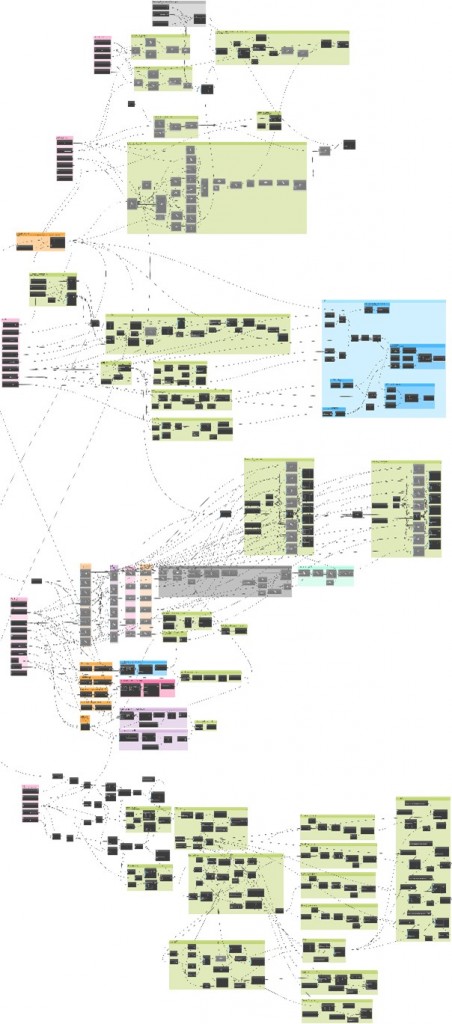
Figure 1: Complete Dynamo Code of the modelled system
Integration of relative positions of the system
As a first step of the integration of various systems, the systems had to be integrated with each other in a 3D space so they could be moved around to take the form of an infrastructure process. For this purpose, the original dynamo script of the individual structures was integrated with 3D geometry translators using Geometry.Translate the function of the dynamo so the geometries can be translated in the 3D space. Figure 2 shows the code snippet for the geometry translation of the columns of the bridge.
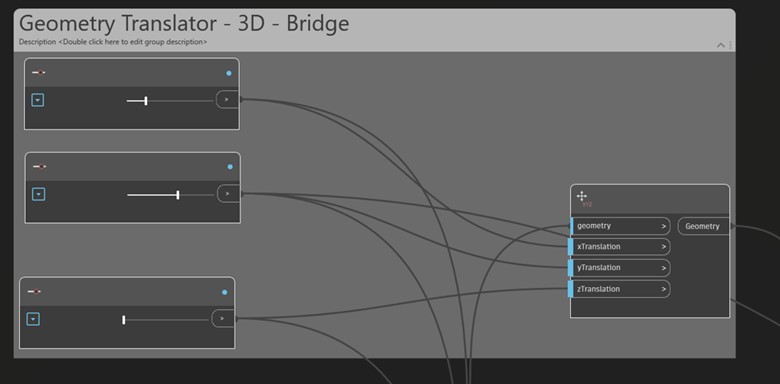
Figure 2
Integration of relative sizes of the structure
The size of the retaining wall changes with respect to the width of the base of the bridge using the code snippet I Figure 3. The width of the bridge deck’s base is fed into the code that changes the size of the components based on the population percentage (Figure 4) the changed width of the bridge deck is then fed into the code block on the top left corner of Figure 3 which then generated the updated x – coordinates of the wall. This allows the wall to change its width whenever the base of the bridge deck is increased or decreased thus connecting both the systems together.
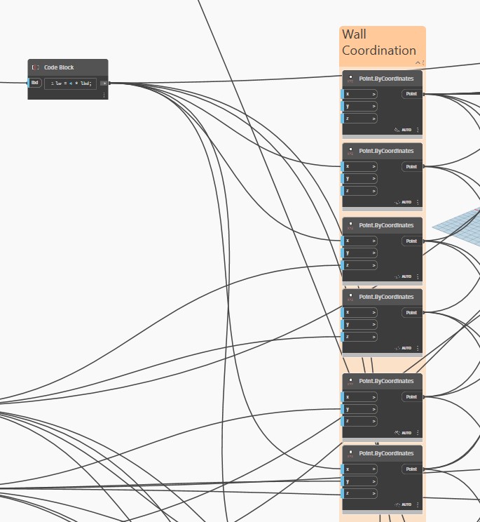
Figure 3: Code to change the width of the wall relative to bridge width
Integration of all systems with a single parameter
The code allows the user to change the size of all the individual elements by changing the percentage increase in the population. The structures are defined based on the initial dimensions for a population size, however when the population increased by x %, the size of all the individual systems also change as per the same percentage. This is achieved by connecting a slider to input the percentage increase in population with the code block that adds that percentage into the dimension defining inputs of all the individual systems. Thus, for example, increasing the population by x percent also increases the width of the bridge, the width of the bridge base & retaining wall along with the size of the frame structure and the size of the tiny house by the same percentage connecting all the individual systems by the amount of population that they can sustain.
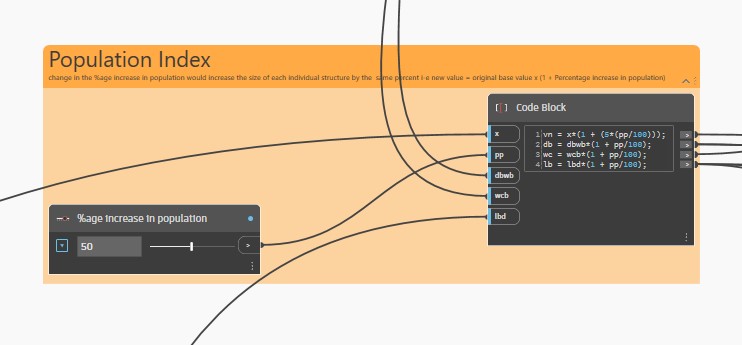
Figure 4
Design Alternatives
The following are the three design alternatives conceived by altering the Population Index.
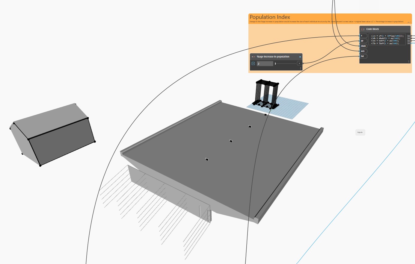
Design Alternative 1 (2% increase in population)
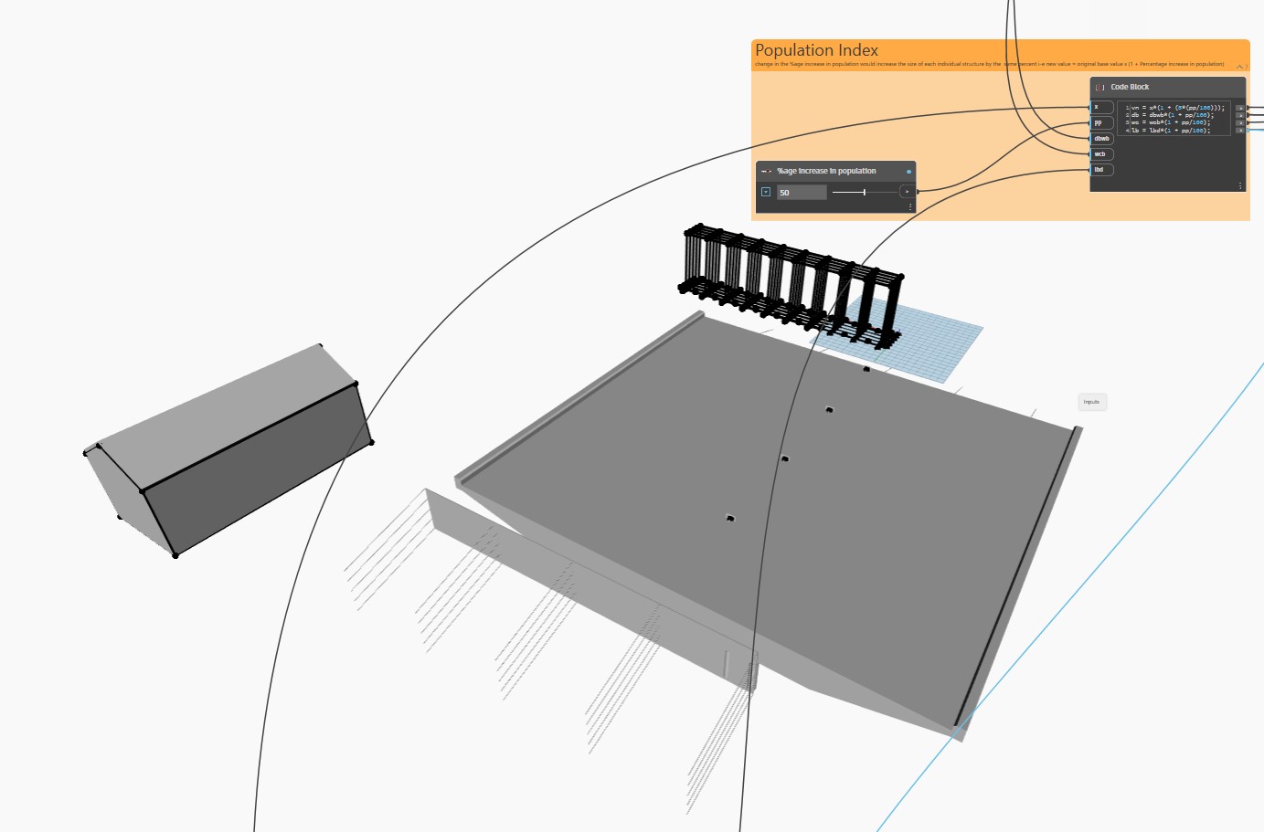
Design Alternative 2 (50% increase in population)
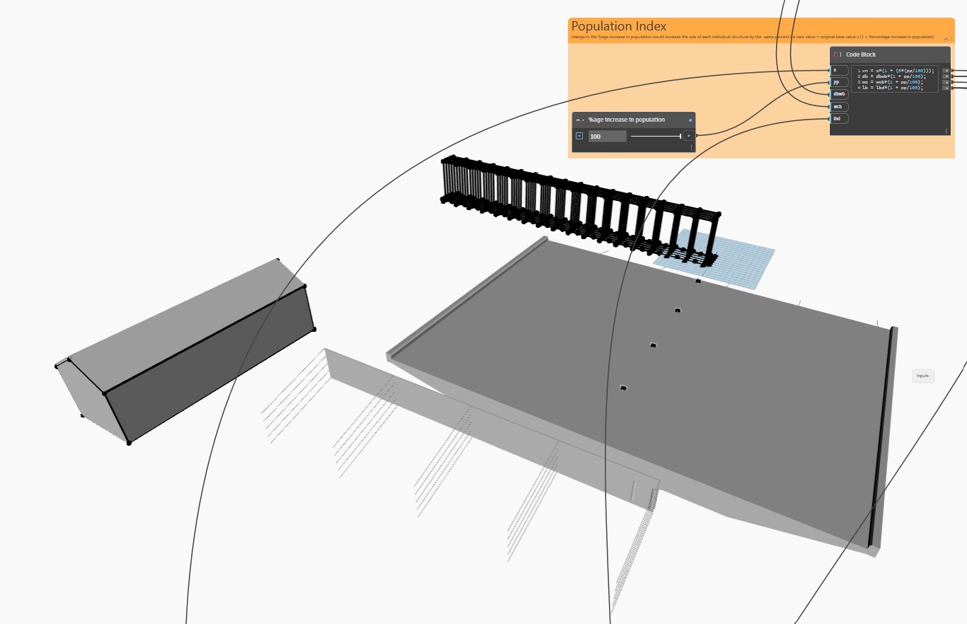
Design Alternative 3 (100% increase in population)
Parametric Model