How does a Solar Updraft Tower work?
A solar updraft tower consists of mainly three components and two physical core principals. First principle is the greenhouse effect which happens when solar radiation penetrates a translucent material like glass, heats up the air or material behind the glass and traps the energy of the heat behind the surface. In a solar updraft tower this phenomena is used on a very large scale under the solar collector roof. At the center of this roof is a high tower located. The warm air from the solar roof flows up in that tower. The height of the tower determines the efficiency of the second physical principle, the chimney effect. The chimney effect happens when pressure on two sides of an object are not the same. Particles will move toward the lower pressure. In a big tower the lower and upper end have a different surrounding pressure and particles, in this case the air, is flowing upward. The air flow is maximized for a high tower and a high air temperature. The third main component is a single, or a number of turbines at the bottom of the tower which turn the airflow into electrical energy. To maximize the power output, its possible to add water tubes under the collectors on the ground to heat up water during the day and turn that heat into longer airflow in the evening and night. [2]
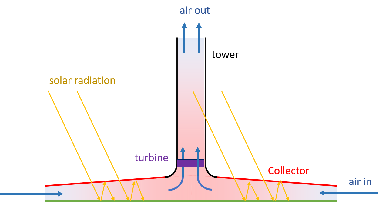
Fig.1: Scheme of Solar Updraft Tower
Ontology of a Solar Updraft Tower
What is the purpose?
Solar updraft towers are not a new technology, but they are not yet used on a larger scale. There are some test locations where they were constructed, but they only serve scientific purpose. This ontology should create a basic ground set of necessary components for future scientists to contribute to. So in a first step its to collect knowledge on these buildings from the past and make it easier for future developers or scientists to change or work on a specific part of the system. If someone thinks about the turbine of a updraft tower, this ontology can help to show all the dependencies that have to be looked at.
What is the scope?
The following ontology focuses on the basic components of the solar updraft tower and their relations.
Who are the intended users?
The intended users of the ontology are scientists who want to contribute to a common understanding of updraft towers. When more information is collected in this ontology it could serve as a starting point for developers to get an idea of what they need to think about, if the want to create such a power generating construct.
What is the intended use?
This ontology should as a common base of knowledge for further development in the area of solar updraft towers. It should give scientists a platform to share knowledge and connect specific research to the complete structure.
Development of an Ontology
On the highest level I structured my project into the three main principles structure, mechanical components and the used materials or other outside factors. The structure separates the building into the two main parts that were identified in the research. First we have the tower. This tower differs from other tower like structures because the hull does not end at ground level and is not connected to the foundation. Rather its hold up by a number of columns. This lower connection columns I modeled separately in the ontology because they are the combining structure that links tower, collector roof and possibly the turbines. The components, because they are distinct structures, have to be disjoint from one another.
I also included the possible materials for different structures. Here the concept of property domain and range are integrated to link the structures with their possible construction materials. This material class is possible one, where a connection to an already existing ontology of building materials would be good to integrate. There are no new building materials used in the construction of updraft tower plants so a already existing ontology would be efficient and probably more complete.
Because this ontology is rather a base to have a common ground of understanding of a updraft tower and not a tool to create a instance for construction out of, the concept of instances are less important. I created some instances for simple classes, to show what is possible with such an ontology, but at the current research phase of updraft towers its not necessary to already define specific instances with properties. Design options should be discussed first on a higher level of abstraction. Going into detail too much can maybe even limit the range of design options and make possible better options unavailable because they don’t fit the created instances.
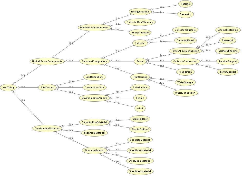
Fig. 2: Representation of the resulting Ontology [taken from Protégé] 
Parametric Modell of a Updraft Solar Tower
Goal and Scope
The updraft tower, as a power generating structure, has its main purpose in generating the most electrical power with the least amount of investment cost. The investment cost is strictly tied to the size of the tower and the area of the collector field. Of course the power generating turbine has a rising cost with higher performance and makes up around 15% of the whole investment cost but is tied to the size of the tower and collector. The parametric model should generate a physical model of the main updraft tower components and generate criteria for energy output and material costs.
Modelling of the Tower
The Tower is a very basic tower. The height of the tower starts at the upper end of the supporting columns. Therefore the upper end of the tower is higher than the input parameter tower height. The wall strengt is not a input parameter. Of course in reality the lower parts of a concrete tower would need a larger wall thickness. To keep it simple in this first step the tower is a straight tube. The tower diameter can be changed an would probably need to be optimized for the later air flow. In [3] a possible tower model for very high towers is introduced. A 1000m tower is estimated with a wall thickness of 0.3 m at the top and 0.65 m at the bottom. As we can see, there is a difference, but a rough average is a good start.
As a way to showcase whats possible with the parametric model, i added color to the tower columns depending if they would withstand the weight of the tower. For this a very simple formula was used to find the strength of the columns and compare that with the volume of concrete from the model. A lot of other factors like wind and the torque are neglected. This should just give a minimum column area. Nevertheless this could later be filled with better formulas to do basic performance checks.
Modelling of the Collector Field
The collector field is in theory a circular structure of panels that are held up by a number of smaller columns. The problem here was, to divide the area into single panels. The easiest form to model in Dynamo would be, to divide the circle into circular sections. This generate the biggest area for a given diameter. Problem with the panels is, that they have curved edges and are in a different shape for every ring going to the outside. Also the outer panels would be far bigger compared to the center panels. The next version in V2 gets rid of the circular edges but still has a lot of different sized segments. The best solution for the production would probably be to divide the circle into squares (V3). If they are all uniform, the production cost and time can probably be reduced significantly. For this solution the algorithm work was a bit higher, but the outcome greatly increases the solution as a model and for future usage.
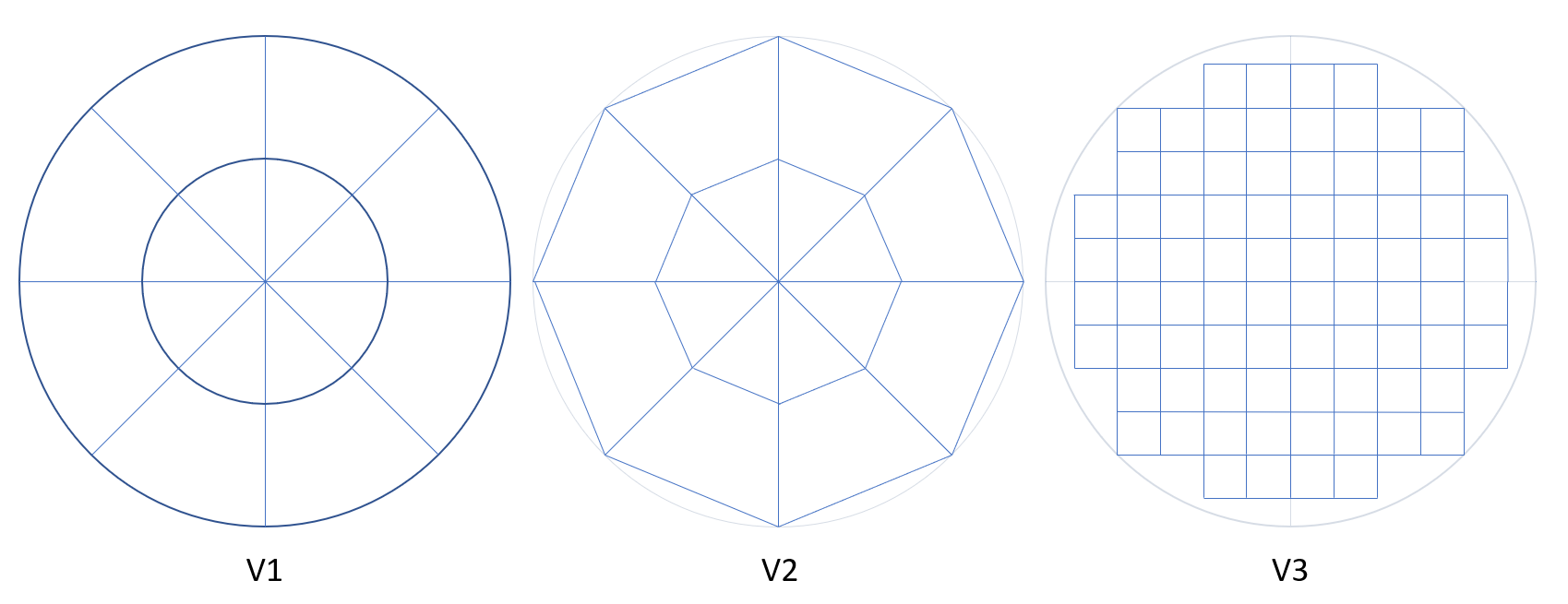
Fig.3:Filling a circle with collector elements [author’s diagram]
High Performance Criteria
The output parameters, as stated higher up, are the amount of material used for this project. This will be a big factor in the overall cost of such a power plant. As output parameter for the electrical output a basic formula that is described in [1] is used. It calculates a performance factor from the changing variables tower height and collector diameter. To translate that factor into a real electrical output a number constants, efficiency coefficients and the average solar radiation for the specific construction site are necessary. These can change for every project but the relation between tower height, collector area and theoretical power output stays the same.
Sources
[1] J. Schlaich, R. Bergermann, W. Schiel, and G. Weinrebe: Design of Commercial Solar Updraft Tower Systems—Utilization of Solar Induced Convective Flows for Power Generation. 127 (1) (2005), 117–124. doi: 10.1115/1.1823493
[2] G. Weinrebe, R. Bergermann, and J. Schlaich: Solar Updraft Towers. In: Encyclopedia of Sustainability Science and Technology. Springer New York, 2021, 1–32. doi: 10.1007/978-1-4939-2493-6_682-3
[3] Th.W. von Backström, R. Harte, R. Höffer, W.B. Krätzig, D.G. Kröger, H.-J. Niemann and G.P.A.G. van Zijl: State and Recent Advances in Research and Design of Solar Chimney Power Plant Technology. VGB PowerTech 7/2008
See also other individual systems:
Or main topics: