In order to create a pleasant climate in both the residential building and the event hall that meets the respective user specifications, simple ventilation by opening and closing the windows is not sufficient. Therefore, an electronic ventilation system is installed in both buildings.
These are installed in combination and with different dimensions. While in the residential building the focus is on heat recovery and thus on reducing energy and emissions, in an event hall it is important to create the highest possible air exchange rate, depending on the type of use. The animation shows the basic components of a decentralized ventilation system with heat recovery:
In our construction, we define that the dimensions of the fan, and thus the volume of the airflow, as proportional to the other components of the simplified model of the DVS. These components are “tube”, “heat recovery module”, “filter” and the “wall panels”. This refers not only to the diameters of the components, but also to their thickness. Excluded here are the wall panels, which have a thickness of 2 cm in any configuration, and the Tube, which can only be configured in length. and diameter. Both components are independent of the performance of the DVS and do not need to be proportionally adjusted to the fan. The only set parameter, is the heat recovery rate. Modern recovery modules are made for a heat recovery of 90%. For this purpose, the modules are set to half the length of the tube, to fulfill this requirement, while the fan is set to 30% and the filter to 20% of the length.
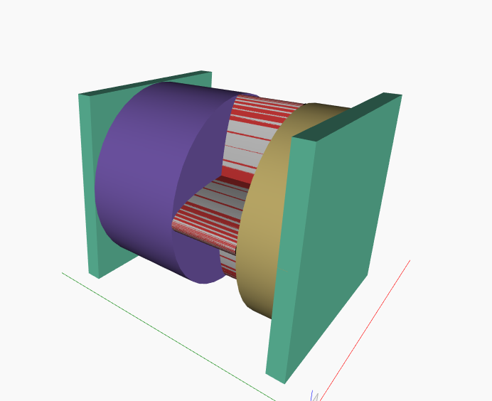 Figure 1: Sketch DVS
With the parametric configuration of the individual parts, an ascending motor classification results, which requires greater motor power with greater air volume flow. For the residential buildings, a smaller and quieter configuration is certainly more suitable than the large and noisier variants of the event hall. The minimum configuration is a 15cm Rotor configuration with 18m³/h air flow, while the maximum configuration is a 50cm Rotor with a 63m³/h air flow rate.
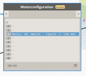
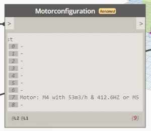
Figure 2: Motor configurations

