Scaffolding systems are temporary structures which enable various types of access and working area for, among other purposes, building or civil infrastructural projects. Due to their temporary nature, their importance and elegance can be overlooked and underappreciated. Despite this, designing an efficient scaffolding system can pose a fascinating engineering challenge, and their success and reliability are fundamental for projects at every scale.
Scaffolding is usually composed of galvanised steel or aluminium (with bamboo remaining prevalent in parts of Asia) and can be broadly grouped into the following types [1][2];
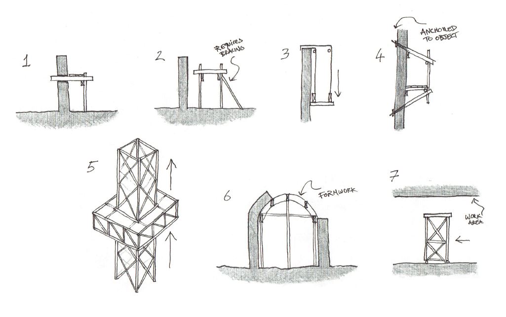
- Single Frame, historical system where ledgers are tied into the work area
- Double Frame, most common type today and the system of focus for this ontology
- Suspended, where a platform is lowered from adjustable cables
- Cantilevered, where the system is free from ground contact, anchored to the object
- Mast Climbing, where a platform climbs vertical masts
- Shoring, enabling the pouring of concrete but also in the erection of masonry arches
- Trestle, for working on the underside of surfaces (think Sistine Chapel), may have lockable wheels today.
Ontological Model
From the point of view of developing a first ontology, a scaffolding system strikes a healthy balance between simplicity (with a limited number of components) and complexity (as it may interface with infinitely different situations). The inherent modularity (with the ability to build systems upon systems) makes for an interesting exploration of various axioms while the limited options of the simple system provide an easy to understand example of conditional statements in developing restrictions within the ontology.
In order to better define the specific ontology scope, the following competency questions and answers were defined.
- What is the purpose?
The purpose of the ontology is to enable the provision of safe platforms at height by a scaffolding supplier to a client. It facilitates the design, construction and deconstruction of an individual scaffolding frame, inferring knowledge about what may be required by adjoining frames given specific design decisions based on predefined constraints, and provides information about safety, timeframe and responsible stakeholders.
- What is the scope?
As there are many varieties of scaffolding system (described above) the scope is limited to a specific chosen Double Frame type of steel and wood system used by the aforementioned supplier stakeholder.
- Who are the intended users and uses?
The users of the ontology are likely to be involved in the planning and design of systems for a clients’ project, although information contained within the ontology may be of interest to other stakeholders. For example, perhaps the person erecting frames may wish to generate inferred knowledge about adjoining frames in order to reserve them for an upcoming project. In turn, other stakeholders are likely to contribute to the ontology. For example, safety inspection personnel may sign off on locking mechanisms being secured in place or update erection dates to reflect delays in a schedule.
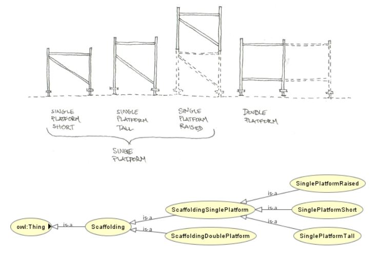
The implementation within Protege concentrated on demonstrating the principles of inheritance through a simple set of 4 options (above). Restrictions were defined so as to make most efficient use of the ontology in terms of sharing common attributes between classes (ie. shared attributes are codified in their highest possible class). The result is minimal duplication as demonstrated by the small number of SubClass Of restrictions within the lower order of classes. For example, the class SinglePlatformTall has just one restriction hasComponent value Standard3200 , having inherited all other required restrictions from ancestor classes. Examples of logical axioms used in the ontology are provided in the following table.
Issues were encountered in the final stages of implementation of the ontology in Protege, resulting in the reasoner failing, causing the error “individual is sameAs and differentFrom another…”. The suspected cause is to do with the ‘exact’ restriction which was essential to the ontology concept. Thus, the .owl file below reflects the aim of the author to implement the concepts described herein despite falling short in terms of solving the logical incompatibility between classes.
SCAFFOLDING ONTOLOGY FULL REPORT
Parametric Model
A simplified subset of parts were considered within the scope of the parametric scaffolding model including fixed module frame measurements, ignoring diagonal bracing and setting a minimum and maximum repetition for the overall system.
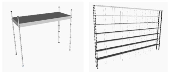
The design challenge was to conceive a user interface which offered flexibility of input for the planner, respecting the fixed modular nature of the system, while providing performance information relevant for ensuring safety and legal compliance. For this reason, minimal user input were provided, consisting of a slider for length of the system, and a list of user input platform heights. These inputs drove the creation of framing to fixed modular increments. Feedback regarding safety was provided to the user in the form of textual warnings which encourage best practice design and code compliance.
Considering that a future stage of the project would require integration with other parametric models, the Dynamo graph was logically documented for comprehension by future users.
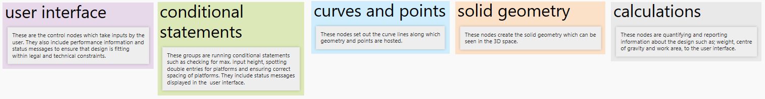
The logic of the entire graph is as follows:
- User inputs drive the creation of points to modular dimensions using several Range nodes.
- These points drive column geometry in modular intervals
- Platforms are composed of girders and deck geometry driven by shapes at points along the centres of curves at level 0 in the Z vector. This seed group is arrayed with a Geometry.Translate node based on the user input list[] of heights.
- The height of the overall scaffolding is in turn driven by a List.MaximumItem of this same user input list.
- A series of conditional statements are encoded to ensure that safety constraints are met, which in turn result in either disallowing (or breaking) the geometry, or by providing status warnings and recommendations, displayed in the user interface.
- Finally, calculations are performed based on the geometry resulting in measurements data and performance metrics being provided to the user interface.
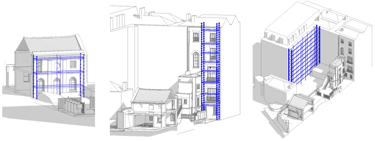
To demonstrate the flexibility of the system, the model was imported into Autodesk Revit and applied to 3 different building typologies. Through these examples it can be seen that the planner has full flexibility to add to the platform list and easily adjust the length with the slider, these being the only inputs required to set out a full scaffolding system with this simple to use tool.
PARAMETRIC SCAFFOLDING MODEL FILE
[1] Webb, B. (2017, October 17). Major Types of Scaffolding in Construction. Avontus. Retrieved from https://www.avontus.com/blog/major-types-of-scaffolding-in-construction/
[2] The Constructor (2020). Types of Scaffolding Used in Construction. Retrieved from https://theconstructor.org/building/types-of-scaffolding-in-construction/11845/