Domain
After the ontological modeling of excavation support systems, the soil nailing system is selected for parametric modeling. With several interrelated parameters affecting the performance of soil nailing, this model aims to support structural and geotechnical engineers in quickly choosing the best design solutions from the design space by balancing several design parameters to achieve specific performance criteria.
Controlling Parameters
The following parameters were used to control the parametric model:
- Shoring height (depth):
The first and main challenge of any excavation is how deep it can be. Although each project has usually one depth, variation of height allows consideration of all excavation cases that can be
resisted by a soil nailing system. - Shoring length:
Another main dimension for soil nailing wall. The decision for length depends on soil condition along the excavation side, and it can be constant. However, the non-homogeneity of soil can make reducing this parameter possible and hence allow engineers to explore more design options. - Nail length to wall height ratio (L/H):
The FHWA defines minimum ratios for nail lengths depending on wall height. Increasing this ratio helps to increase load capacity of wall but also may increase cost and complexity of installation. - Tiebacks vertical spacing (Sh):
Closer spacing of tiebacks (nails) provides more fixity to the wall and reduces deformations, but it may also increase costs and construction time by the addition of nails and walers. - Tiebacks horizontal spacing (Sh):
‘Sh’ is usually less critical to design than ‘Sv’ since the structural analysis is made in the vertical direction. However, horizontal spacing controls the distribution of pressure on nails but also
works against cost and construction time similarly to vertical spacing. - Inclination of tiebacks:
This defines the vertical angle of which the nails are embedded into soil. Steeper angles enhance load capacity but may increase the potential of sliding and construction difficulties, and
vice versa.
Other parameters could be considered, such as shotcrete, grout injection, steel plate thickness and nails and waler bars diameters. However, they are neglected for simplicity, submission due date and the relatively minor influence on design.
High-Performance Criteria
The alternatives will be evaluated against two different criteria:
- Quantity of steel nails: the total weight of steel nails in the model is calculated, which gives an indication about the cost of materials for each alternative
- Force-to-Resistance ratio: the maximum tensile force on nail is estimated over the value of pullout resistance (bond strength of nail considering full length). This ratio indicates how close
the estimated load is to the capacity of the nail.
Parameter in Dynamo
Visual programming with Dynamo is created by linking nodes where each represents a certain
function that usually pass a geometric command. Nodes were grouped in the model depending on
their type and scope as follows:
- Input Parameters:
Number-slider nodes allow us to manually change values for each of the six defined parameters, where each change defines a different alternative in the design space. - Shoring height definition:
The starting axis in the global -z direction is generated based on the specified shoring height parameter. - Shoring length definition:
The end axis in the global +x direction is generated based on the specified shoring length parameter. - Tiebacks distribution:
Center points for nails are generated along the global xz plane based on the specified nail spacing parameters and assuming a cantilever distance of 0.5 for the first row of nails. - Walers distribution:
Following the distribution of nails, two vertical and two horizontal lines are generated with an offset of 0.25 from the center points of nails, representing waler reinforcement bars. - Tiebacks length & inclination:
Lines in the global yz plane are generated based on the nail length from L/H ratio and are inclined towards the global –z direction by the specified nail inclination parameter. - Creation of surfaces:
A flat surface in the global xz plane is created, representing the whole soil nailing wall, and a cylindrical surface is created around each nail with a diameter equal to the drill hole (0.127),
representing the bonding surface with soil. - Calculating the number of nails (kg):
Nodes to mathematically calculate the total weight of nails based on the number of nails generated and the specified nail length parameter, then a watch node to observe the resulted
output for evaluation. - Determining ratio of maximum tensile force on nails to pullout resistance:
Tensile force will be based on the specified shoring height with fixed assumptions regarding soil conditions. Resistance is based on the bonding surface area that was created in #7.
The following figure shows the parametric model generated by the node groups.
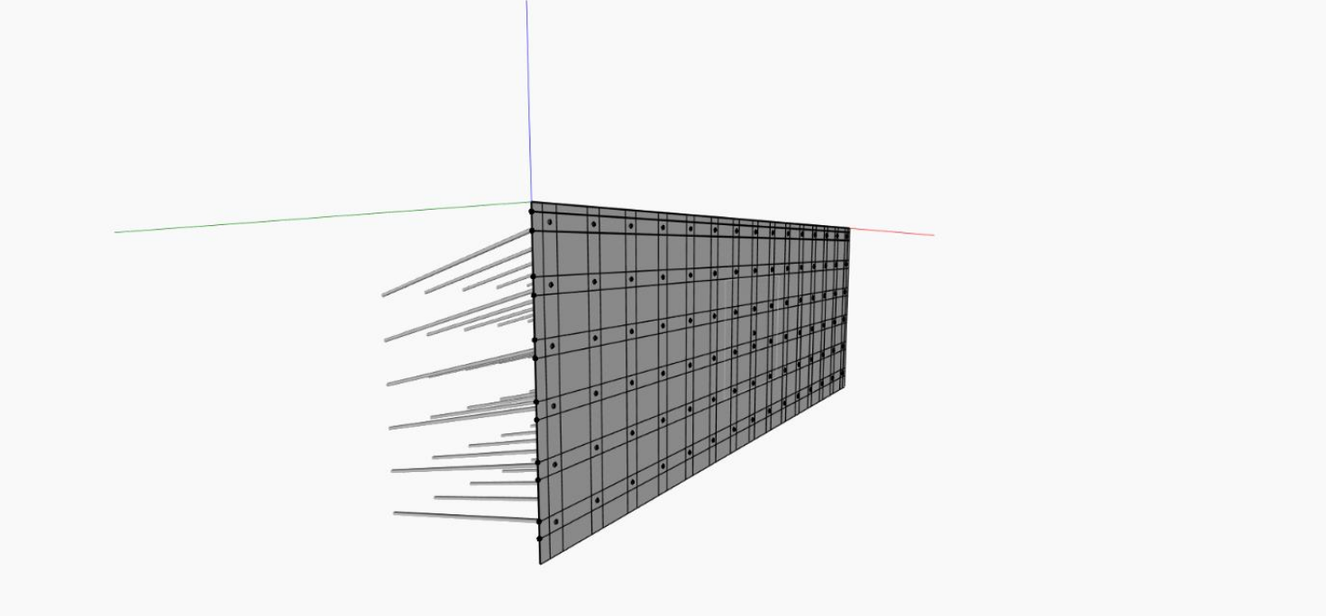
Figure 1: Parametric Model of Soil Nailing System
Design Space
By varying the defined parameters, a range of many possible alternatives is created. Table 1 below shows the specified limits for each parameter.
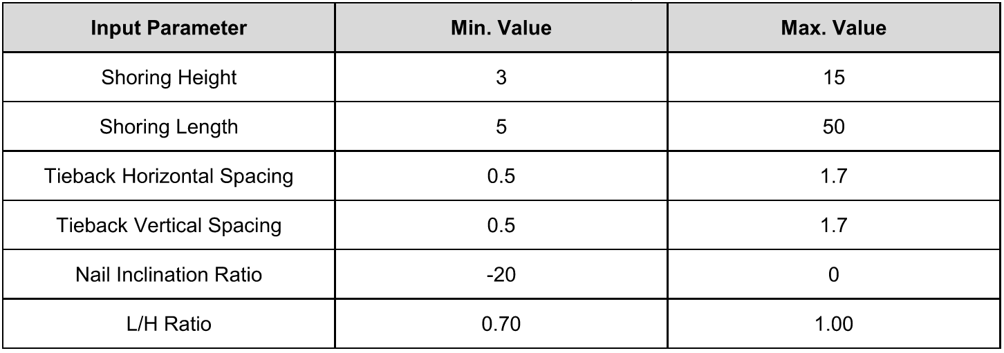
Table 1: Parameter Values Range
Looking at the above table, the number of alternatives can be enormous, even when we assume height and length as constants. Without a tool like Dynamo, we would never dare to observe such vast design space. However, it should be noted that the structural design of soil nailing system is actually very complex, and the major limitation of the model is that it does not consider soil conditions and global stability considerations; in fact, it assumes one set of basic soil parameters to roughly estimate loads on nails and their pullout capacity only. Thus, choosing maximum spacing values and minimum values for other parameters, for example, will generate the simplest design form in terms of feasibility and load-carrying efficiency but regardless of any safety factors for soil stability or bearing capacity. That means that not all alternatives in the design space could be applicable, and it is hard to guess which alternative can be adopted without a parallel geo-structural analysis alongside it.