CONTEXT
Systems:
- Aircraft Hangar
- Train Station
For deciding upon a context in which both civil systems coexists, we took as a priority the expanding of both main functions of each system: storage & travel.
The chosen urban context is that of an airport. The airport counts with multiple hangars for storing aircraft before and after flights, as well as an adjacent train station that offers a way of public transportation for workers and travelers to arrive at the area.
Once the context was defined, it was necessary to think of how the relations between both systems could be established.
After discussing various ways of rearranging the parameters that define both buildings one key factor was decided upon: demand or in other words the number of people that go to the airport. Airports with low demand tend to use smaller aircraft for their flights which leads to smaller hangars needed for storing those planes and also to train stations that do not need a high number of platforms due to fewer people traveling. On the other hand, if the airport has a high demand, the utilized airplanes will be bigger in number and dimensions which leads to multiple bigger hangars and a longer train station with multiple platforms to fulfill the higher demand.
DYNAMO INTEGRATION
Due to the properties and size of both initial models, the combination of both projects was made in one single Dynamo file without the need of the plugin Speckle. The final version of this file can be found at the bottom of the page.
NEW PARAMETERS & DEPENDENCIES
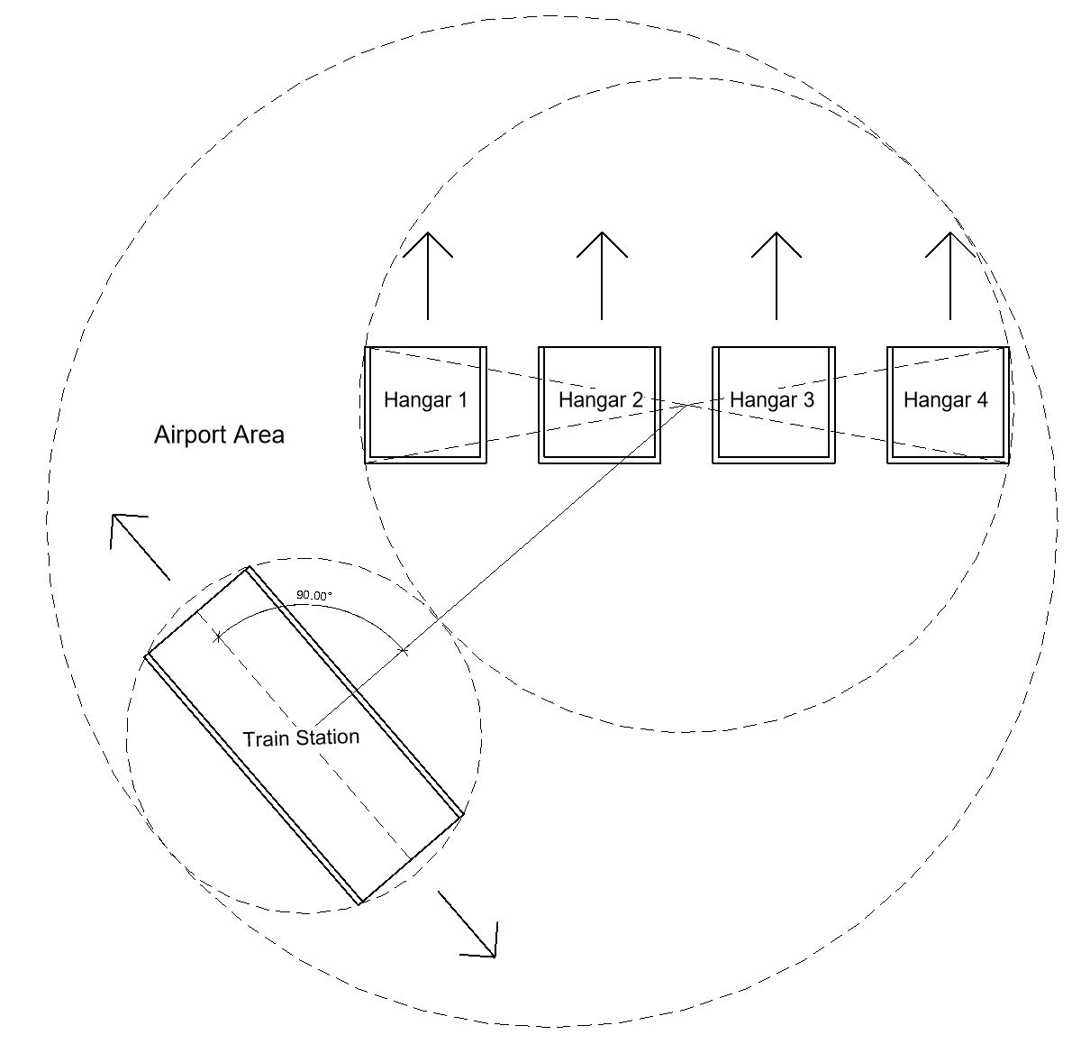
The first new addition to the model was the ability to change the number of hangars situated in the airport. The user can add multiple hangars that will be placed along the X-Axis of the project and stand parallel to the main hangar. All of them possess the same dimensions and the distance between them is that of half the hangar’s width. This provides a safe distance between buildings which avoids accidents.
Once the hangars are placed the inputs for the train station can be decided. The idea is that the size and number of hangars are dependent on the aircraft that will be stored or in other words, can be translated into a number of people that will travel to the airport. This marks the parameters that will dimension the station, thus achieving a dependency between both systems.
The following parameters of the train station were adapted to respond by changes made to the hangars:
- The number of platforms Np: It is equal to the number of hangars divided by 3 and then rounded up (E.g. #hangars = 4, then 4/3 = 1.33 = 2 platforms).
- The length of the station l: It is equal to the length of a line drawn from one corner of the first hangar to the opposite corner of the last hangar divided by 2
- The width of each platform w: It utilizes the following formulas going from the maximum number of people attending the airport at the same time:
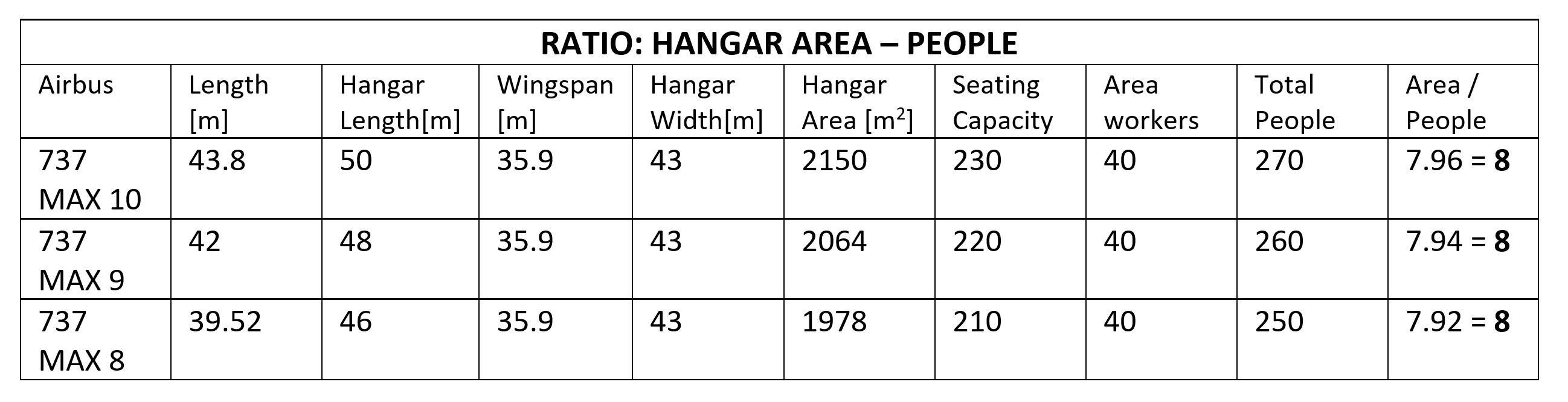
First to get the number of people that will use the station we took the total area of all hangars combined AH and divided it by a factor of 8. This factor was chosen by using a real-life example of Airbuses 737. By utilizing their dimensions and seating capacities [1] a ratio of people to the area in hangars can be calculated (see table 1) and used to calculate the total number of people p.
p = AH / 8
Area A equals the number of people p times 1/3 (density factor which establishes 3 people for every square meter) times 5/4 (a factor that counts for 25% of the platform not being “usable” due to safety reasons, worker’s space, etc).
A = p * 1/3 * 5/4
Finally, width equals area divided by length times the number of platforms plus three additional meters to follow safety guidelines which are used solely for retail space, security, area for workers, etc.
w = (A / (l * Np)) + 3
These three parameters alter the span and length of the station which has an impact on the whole structure of the building and assures that both systems are proportional in size so there is no more space than required.
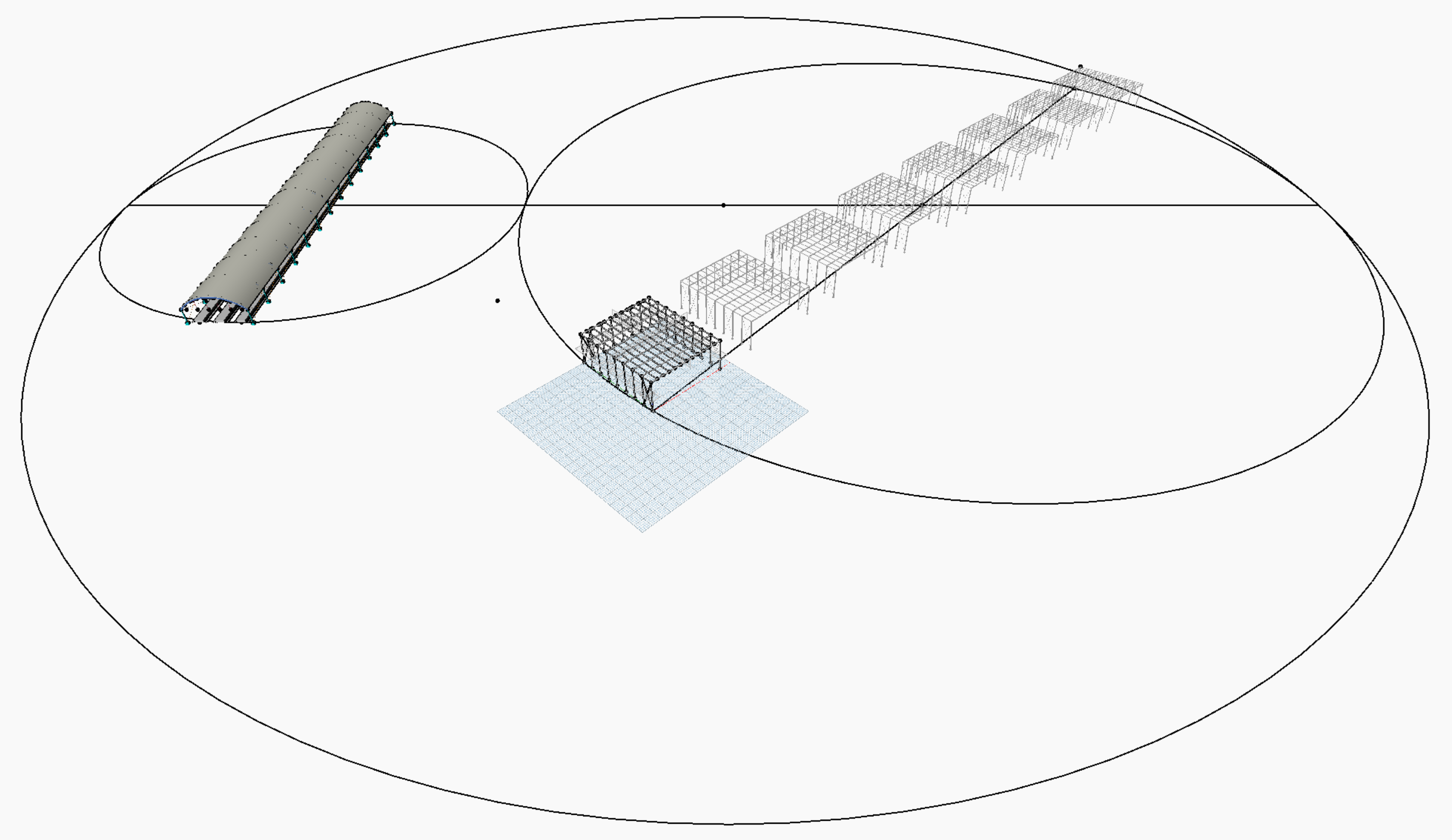
The train station was modified to be placed away from & behind the hangars so that it doesn’t clash with the aircraft’s path and with enough distance to be safe for travelers and avoid the transfer of vibration loads from one building to another (see figure 1).
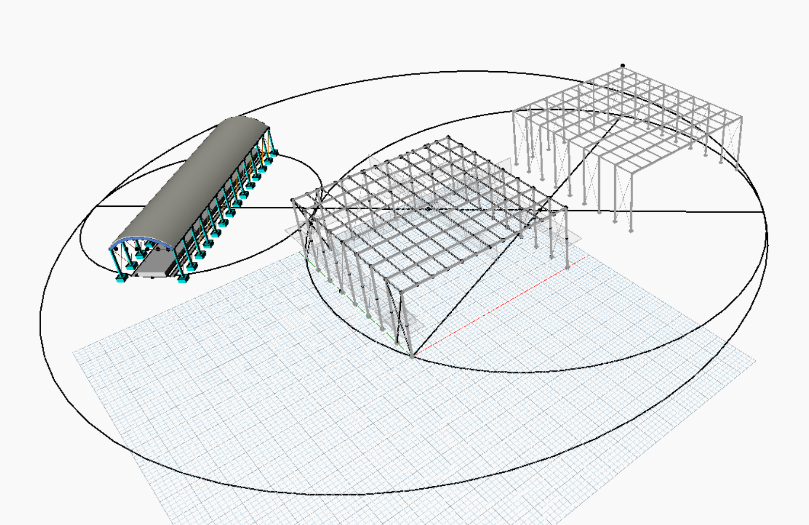
3D VISUALIZATION
The following link lets you download the model and experiment on its configuration directly:
Airport system – Parametric model
VARIANTS & EVALUATION CRITERIA
Three different variants were developed to experiment on the airport’s configuration and to compare results. Note that only the parameters that directly affect the aforementioned topics were varied (so elements like number of beams and columns will remain constant). Please refer to each initial system to see how other parameters work. The creation of multiple variants lets the user evaluate different outputs generated by Dynamo and evaluate them based on user-selected criteria.
Besides the original evaluation criteria for each individual system, we selected additional categories to evaluate the integration of both systems. The first one evaluates the minimum travel distance from the center of the station to the center of the hangars. A balance between convenience and safety as well as security is a requirement. Train stations need to offer the shortest possible path to the hangars without the risk of being too near to where the aircraft is located. Besides, the train station must have in its platforms enough space to fit all of the travelers, workers, and other types of people that arrive and depart from the airport. As an extra criterion, the model also calculates the total area the airport takes from which future cost analysis can be made.
Evaluation criteria for integrated airport system:
- Minimum travel distance for passengers.
- Train station must have enough capacity for all of the passengers.
- Extra: Total area of the airport (see figure 1).
To maintain the variants as accurate as possible we created three different scenarios using the values found in table 1 as a guide:
VARIANT 1 – Small airport: Consists of only two hangars. Each one is designed to store an AirBus 737 Max 8. Number of platforms = 1
VARIANT 2 – Medium airport: Consists of five hangars. Each one is designed to store an AirBus 737 Max 9. Number of platforms = 2
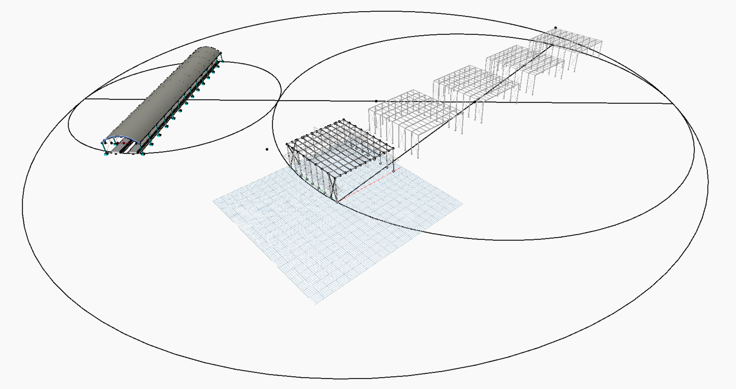
VARIANT 3 – Big airport: Consists of eight hangars. Each one is designed to store an AirBus 737 Max 10. Number of platforms = 3
To see the specifications of each hangar relative to the aircraft it stores please look at table 1.
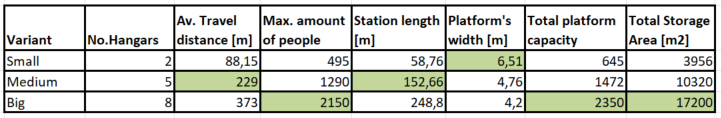
The following table summarizes the results generated by each model:
CONCLUSIONS
While increasing the number and size of the hangars certainly optimizes the maximum amount of people and storage capabilities of the airport other variants were not the most optimum ones. The 2nd alternative (medium) provided a shorter average travel distance of ca. 150m. This distance is not only safe enough for both systems to coexists without risks but also offers the passengers the most comfort by giving them a shorter walking path. At the same time, the average length of platforms in Europe is usually between 110 and 140 meters long which makes the 2nd alternative more suitable for a real-life environment as this length is usually dictated by the maximum length of trains that go through that station. a 248.8 m long station is unpractical as trains are not that long. Last but not least the 1st variant (small) showed wider platforms which on one hand are safer for the end consumer and on the other more practical for the project developers as it reduces time and costs of constructing additional platforms.
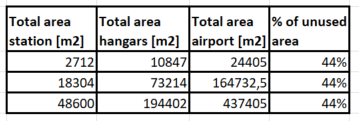
Looking at the utilized space table (table 3), however, it can be noticed that it doesn’t matter how the dimensions of the station and the hangars are altered the amount of unutilized space in percentage remains constant at about 44%. In a small airport, this represents 10738 m2 of land. In a medium-sized airport, this number is over seven times bigger at 72482 m2 and finally, a bigger airport showed almost three times that area with 192458 m2 of unused space. It is to be noted that this space in an optimized model with more systems integrated can be reallocated to other elements like terminals, hotels, cargo areas, landing areas, etc.
Evaluation points of the generated alternatives summarized:
- Big airports allow for higher demand and have a higher amount of aircraft storage.
- Medium airports provide a good balance between safety and convenience for all parties involved.
- Small airports do have the most comfort for travelers but the distance between hangars and the station is smaller than the optimum.
- All types of airports show the same percentage of unused space (44%) which is relative to the size of the airport
REFERENCES
[1] https://www.boeing.com/commercial/737max/