1. Introduction
A district heating system is a system in which heat generated at a centralized location is piped to homes for heating. In Berlin, district heating is an important part of residential heating; district heating has become the main source of heating in city centers.
The project considers different ways of using natural gas for heating, i.e. thermal boilers,National thermal power plant and cogeneration systems(CHP). In addition, piping is an important part of the system. Therefore, rigid polyurethane (PUR) foam insulated pipes and poly to thermoplastic (PET) foam insulated pipes were also selected for the study.
2. Objective and scope
The functional unit is defined as the production and operation of 2.42 DN100 prefabricated insulated pipes to provide 7.5 GWh of heat per year to a building with a total heating area of 230,000 m2 , including the required materials and energy;
The system consists of the main, community and building networks, totaling 1.2 km of prefabricated insulated pipes. The heat sources are interface CHP (2.5 MW heat) or boilers (7.5 MW heat) or a national thermal power plant using homogenized natural gas, respectively.
The Boundary Pipes theme of this study involved multiple stages, from raw material collection to the production of the pre-insulated pipes. This includes the extraction of raw materials such as steel, HDPE, aluminum foil, copper, and electricity; the production of core intermediate materials such as welded steel, polyurethane foam, and PET foam; the transportation of the materials to the production site; and the assembly of the materials into the finished pipe. Piping does not include the use and production phases. Heat source components are considered only for energy consumption and greenhouse gas emissions during operation.
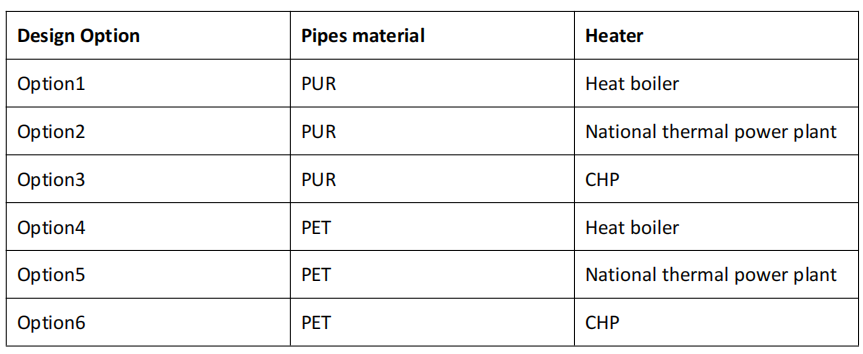
3.Design options
4. Life cycle inventory
The amount of pipework is the value at 1.2 km.
The heater is only considered for emissions during the operating period and therefore not for quantities; the emissions are consumed during the annual operating period, i.e. the heating period.
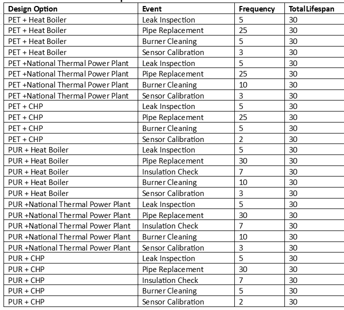
5. Interventions and longevity
6. Life Cycle Impact Assessment
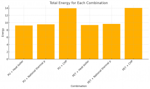
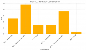
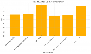
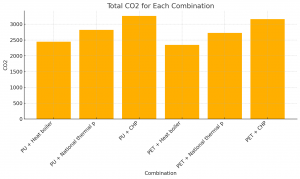
The figure shows the annual energy and CO2, SO2, and NO2 emissions. The results show that a cogeneration scenario involving any type of pipeline would result in higher energy consumption, CO2 and NO2 emissions. This may be due to the fact that CHP operation requires more complex equipment and higher fuel consumption.
As for piping materials, there were no significant differences in overall emissions; however, sulfur dioxide emissions were significantly higher for polyurethane compared to PET. This could be
This is due to the fact that the main components of polyurethane foams are isocyanates and polyols, the production of which may be associated with higher consumption of fossil fuels (e.g., coal and oil).
7. Hierarchical analysis method
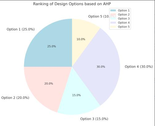
In the overall evaluation, the higher the relative importance, the better the overall performance of Option 4, followed by Option 1 and Option 2. this suggests that the combination of PET and thermal boiler is the optimal choice. Although the thermal boiler is less energy efficient, it may perform better in some key emission indicators such as SO 2 and NO 2 . Although PET pipe is thicker, the production process is relatively stable and long-term operation and maintenance costs may be lower than for PU pipe.
