The .dyn file for the parametric model can be found here.
You could also download the parametric model and the ontology here.
The considerations for the integration context of the five systems were already oriented towards an implementable approach for the parametric model. The integration context is the basis of the development of the parametric model.
Design Challenge
Since five systems were combined to one Tramway Infrastructure the parametric model includes many design parameters that change the geometric embodiment of the model. The Tramway Infrastructure input parameters with adjustable values are:
Tram Track:
- Sleeper Spacing: 0,6 – 0,8 m
Steel Bridge:
- Length: 50 -150 m
- Peak Height: 15 – 35 m
- Segments: 1 -39
- Radius Diagonal Members: 0,01 – 0,15 m
- Height Top Chord: 0,01 – 0,25 m
- Width Top Chord: 0,01 – 0,30 m
- Thickness Deck: 0,1 – 1,0 m
Retaining Wall:
- Heigth: 4,5 -15 m
- Thickness: 0,1 – 2 m
Base Courses:
- Height: 0,5 – 3 m
- Side Slope Factor: 1,5 – 2
Tram Dam:
- Shoulder Height: 1 – 6 m
- Proctor Density GU: 1,9 – 2,2 t/m3
Foot Bridge:
- Width Deck: 2 -5 m
- Thickness Deck: 0,5 – 1,5 m
- Width Column: 1 – 5 m
Some of the input parameters from the initial systems are defined by output parameters of the other systems since there are geometrical dependencies between the five systems. Those dependencies are specified in the description of the modelling process.
To be able to compare and evaluate different design options of a Tramway Infrastructure, high performance criteria for the combined model had to be defined. The initial criteria for the tram track were the sum of the costs and the CO2 consumption of the different system components that mostly depend on the weight. For the tram dam, the vertical dead load and the total dead weight of the earth body were compared. In the foot bridge model, the observance of the capacity of the middle column and the ramp angle were controlled to evaluate the suitability of the design. Costs and CO2 consumption were chosen as high performance criteria for the combined Tramway Infrastructure to enable users to evaluate different design options. These can be used to make statements about the economic efficiency and the environmental impact. The values used to calculate these factors depend on the materials or components and are listed in Table 1. From the systems in dynamo, different quantities (such as volume, length or number of pieces) must be generated depending on the component.
Table 1 Component and material properties (weight, costs and CO2 consumption) per unit [Own Illustration]
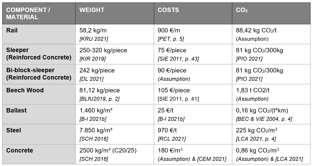
For concrete, only a value for reinforced concrete was available [LCA 2021]. Therefore, the following rough assumption was made for the value of CO2 consumption for concrete without reinforcement:
135 kg of reinforcement for 1 m^3 concrete [LCA 2021] with 7850 kg⁄m^3 density for steel [SCH 2016]:
(135 kg)/(7850 kg⁄m^3 )=0,0172 m^3 -> 1,7 % of the volume
CO2 consumption for cement, fly ash, coarse and fine aggregate:
0.822+ 0.0025+ 0.016+ 0.0053=0,8458 kg CO_2/m^3
0,8458 ∙ 1,0172=0,86 kg CO_2/m^3
For the price, a rough value was chosen based on the values of a manufacturer plus the missing value-added tax [CEM 2021]: 150 €⁄m^3 ∙1,19≈180 €⁄m^3 .
Modeling process
To allow a clear and organized working space in Dynamo BIM, the groups and nodes were transformed into custom nodes for each single system. As a first step the starting point of the steel bridge was connected to the end of the dam routing. Therefore, the coordinate system of the routing curve was adopted and adjusted in the ”SteelBridgeDesign”-custom node. Then the tram track was added in a way that it was modelled directly on top of the dam routing and the steel bridge curve. Since the computation time was way too high to create the tram track with all its sleeper elements across the original dam routing, the routing was changed to a smaller section with only one curve. To further minimize the computation time while working on the model, the distance between the sleepers was temporarily set to an unrealistic high value. For the whole system of a tram dam, the base courses between tram track structure and dam body had to be created as additional system. The crest width of the base course body included the width of the tram track plus 0,7 m safety distance on each side of the track system oriented towards the EAÖ [1, chap. 3, p. 24 – 34] (safety space in the road cross-section for road integrated tram tracks). The width of the lower side of the base courses depends on a side slope factor and the height of the base course body. The values of those input parameters are assumptions since the base course body is only an additional part of the system. The upper side of the base courses had to be angled with the same factor as the cross slope of the tram dam, which was implemented in the custom node depending on the tram track system. For the setting of the tram track type (slab or ballasted), a boolean switch was created as a global input, since the tram track system influences not only the tram track, but also the cross slope factor of the base courses and the tram dam. The crest width of the tram dam has to be predetermined by the base width of the base courses. This is why a first approach, where the global coordinate system was located in the base of the tram dam and the whole tram/base courses/dam body-system was created from bottom to top, showed a cyclic dependence and had to be adjusted to the previously described approach. The dam receives the proctor density of the GU material and the shoulder height as parameterizable inputs, which do not depend on the other systems but on the earthfill material and the adjacent terrain. Almost all parameters of the steel bridge are selectable independently of the other system. For the width of the bridge, the width of the tram tracks plus the safety distance of 0.7 m on both sides is passed. This bridge width in turn determines the width of the retaining wall. The thickness and height of the retaining wall depend on the slope or terrain and are therefore independent of the other models. The foot bridge has been designed in a way that it can be moved along the route of the dam by the parameter “position distance”. Within the custom node it is set that the foot bridge always keeps a freely chosen minimum distance of 20 m from the transition between the dam and the steel bridge. The height of the foot bridge is determined by the height of the dam body/base course/tram track-system plus the structure gauge for the passing of the tram. The dimensions of the structure gauge with 4 m height and 3,25 m width were oriented towards [1]. As the tram dam can only pass underneath one half of the footbridge next to the column, the total length of the bridge must be unrealistically long if the required ramp angle is to be maintained. To overcome this problem, an access height was introduced as a parameter, which allows the starting and ending point of the bridge deck to be moved upwards, which automatically reduces the angle. One last general point to note was that all units were uniformly changed to meters (there were models with inch or cm).
Design space and alternatives
The parameters for the three design options were chosen in a way that demonstrates the variety of possible model modifications and was oriented towards three different design challenge contexts. For the design of the foot bridge, the ramp angle was controlled via a watch node in Dynamo and the inner and outer distance were adjusted until the minimal length of the foot bridge that observed the ramp angle value was found. Table 2 and Figure 1 compare the parameters and the visualization of the three different designs.
Table 2 Input parameters of design option 1 – 3 for the Tramway Infrastructure Model [Own Illustration]
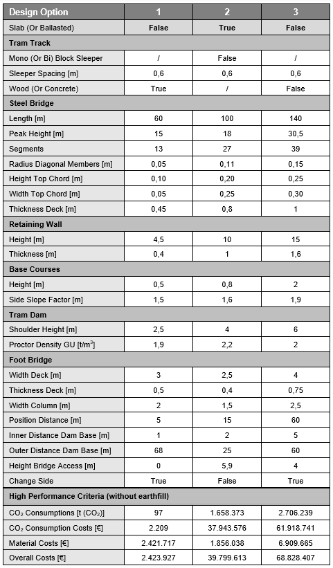
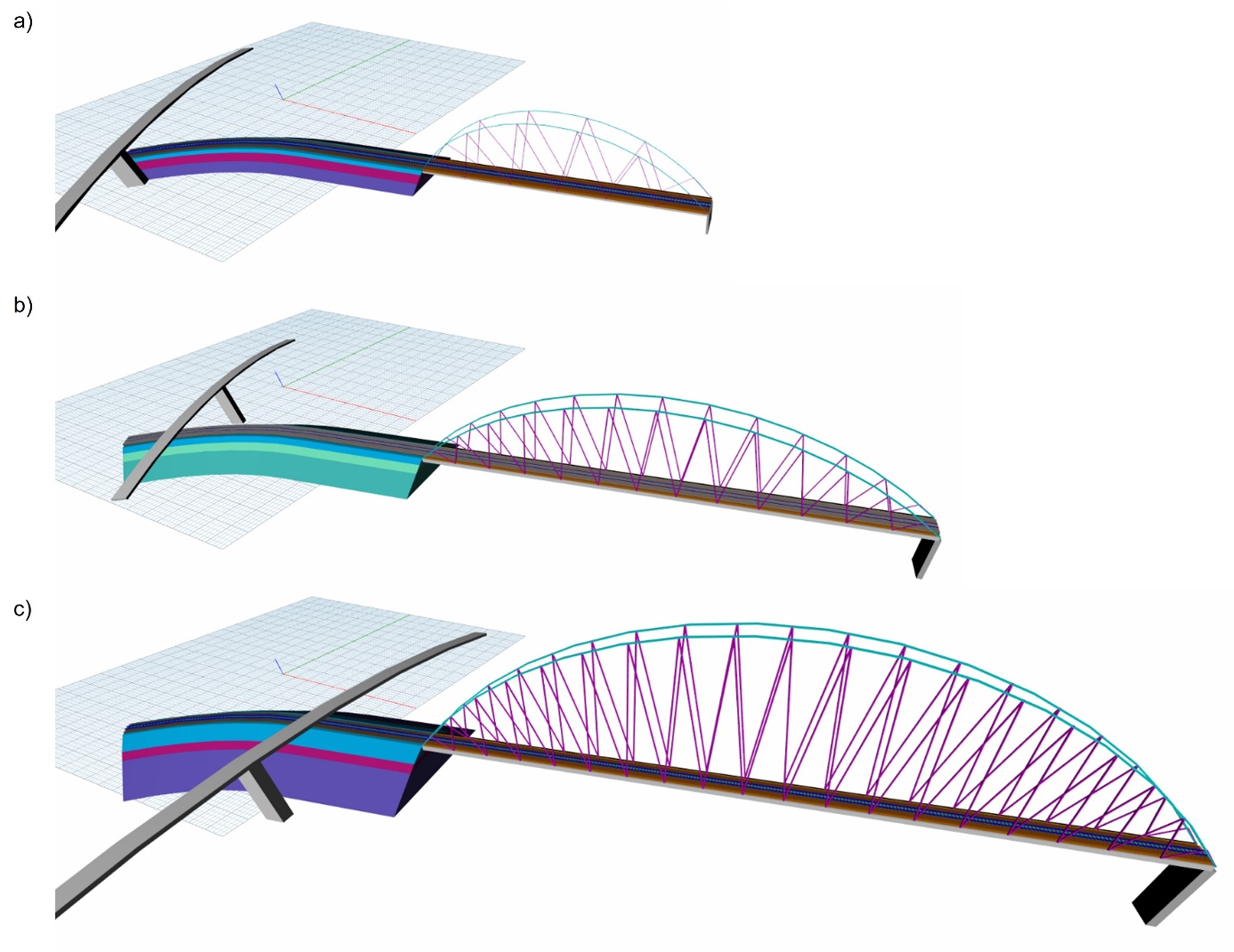
Figure 1 Visualization of design option a) 1, b) 2 and c) 3 with the same scale [Own Illustration with Dynamo]
Option 1: Small tram dam with a ballasted track and wood sleepers that is led along a small steel bridge with a short retaining wall. It can be crossed via foot bridge which starts and ends at the same terrain level as the tram dam. This option could be designed in areas where the terrain is relatively even and the tram route has to cross e.g. a river or a small valley. The pedestrian bridge with its high length is only economical if it also spans other obstacles such as a road.
Option 2: Medium tram dam with a slab track and bi-bock-sleepers that passes over a steel bridge with a medium span. The dimensions of the retaining wall are bigger to support a greater leap in terrain. The foot bridge has higher access points on both ends, which is why the length of the bridge deck is smaller by still observing the ramp angle. This design challenge could occur if parts of the terrain surrounding the dam are higher or the foot bridge can be accessed via stairs.
Option 3: High tram dam with a ballasted track and sleepers made from reinforced concrete that leads over a large steel bridge. The foot bridge has slightly higher access points but to observe the ramp angle the bridge needs a long span. This option can be used for greater terrain unevenness, which is why the retaining wall also has larger dimensions.
Figure 2 shows the structure of the output of the high performance criteria with an example for design option 1. Table 1 compares those criteria for the three different options. This demonstration shows that the model can be used to compare and evaluate material costs and environmental impact, measured by CO2 consumption. Users can apply their own weightings to these factors to select a fitting design option.
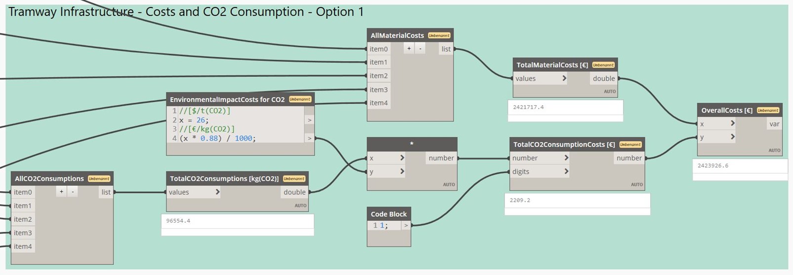
Figure 2 Output of the high performance criteria in Dynamo (design option 1) [Own Illustration with Dynamo]
Boundary conditions
Since the model is only a representation of reality and several assumptions and simplifications have been made, it is important to define the boundary conditions. In the presented model the standard-dependent values of the tram dam design, like the side and cross slope factors, were taken from the Ril 836 [2] since the initial dam was designed for railway use of the Deutsche Bahn. Those design values for the tram dam would have to be aligned with the EAÖ [1] and adjusted if necessary. Since the base courses were only necessary to connect the initial systems their values for the input parameters – side slop factor and height – were not further considered for this model. Their limit values would have to be determined according to the standards of the EAÖ. According to the Ril 836.0504 “Übergänge zwischen Erdkörpern und Kunstbauwerken” [2] there has to be a transition element between the earth dam and the bridge that compensates for the different stiffnesses and settlements that occur. Even though this element is also assumed to be relevant for the tram dam in this context, it is neglected to simplify the model. Other design specifications, such as the required curve radii for the routing of a tram and the lateral inclinations of the rails to be taken into account in curves as well as the resulting inclined structure gauge, are neglected. Furthermore, the model assumes a single-track, two-directional operation of the tram line. Depending on the design conditions a double-track system and therefore a widened dam and steel bridge might have been an option but was not considered due to the increased computation time. Steel bridges become more economic for longer spans. However, in the presented integration context a short bridge seems more likely, which is why the span is limited in the model. For a more realistic design challenge the use of different types of bridges with different materials would have to be investigated. The initial dam model was developed for outer-city areas, where large dams with a maximum of 12 m shoulder height would be realistic. Since the integration context fits more in a suburban area, the maximum shoulder height is reduced as well. The foot bridge was designed to span over a six-laned main road with a column between the two directions of the traffic. Because of the column only one half of the foot bridge spans over the tram dam. Therefore, this foot bridge design is only efficient if there was a road or some other obstacle next to the dam that also has to be crossed. If the foot bridge is only to span over the tram dam, a different bridge design would have to be developed, as this type of bridge would be uneconomical with a span twice as large as necessary. For the two bridges, the individual components were not considered separately, but the prices and CO2 consumptions for steel and partly concrete were used for the total volume. In reality, the volumes of all components would have to be calculated individually and prices for the more precisely defined components (cables, cross beams, top chord etc.) would have to be used. If the model is to be used to design a real construction project, the costs and CO2 consumptions of the previously specified materials for the dam fill and base layers can be included in order to be able to consider the entire project.
Outlook
The model can be improved and expanded by researching the simplifications made in more detail (like the base course component). Integrating different bridge types with different materials for the foot bridge and the tram bridge would allow for extensive comparison and evaluation. If longer calculation times are not a problem, significantly longer tram routes could be modelled. For this purpose, the model could also be extended for the inner-city area. Other net elements like tunnels could be integrated as well. As mentioned in the description of the integration context the parametric model could easily be adjusted for railway or road use. To do so the tram track system would have to be adjusted oriented towards the corresponding standard instead of the EAÖ [1]. The model could also be modified in a way that compares the economical choice between a traffic bridge or a traffic dam, since this is a common question regarding construction projects in uneven terrain.
Although many assumptions and simplifications were made for the model, it was possible to demonstrate the potential of an overall parametric model that can be used to evaluate design options based on selected criteria. Merging individual more elaborated models could play a major role in the future. However, this would probably be difficult to realize with the help of Dynamo at the moment due to the high computational effort. The benefits of parametric modelling were nevertheless well demonstrated.
References
[1] EAÖ 13: Empfehlungen für Anlagen des öffentlichen Personennahverkehrs, Forschungsgesellschaft für Straßen- und Verkehrswesen (FGSV), Arbeitsgruppe Straßenentwurf. 2013.
[2] Richtlinie 836 (Ril 836): Erdbauwerke planen, bauen und instand halten. Publisher: DB Netz AG, Deutsche Bahn Gruppe. 1999.
[B-l 2021a] BAUSTOFFE-LIEFERN.DE (2021a): Bedarfsrechner Schotter. Available online at https://www.baustoffe-liefern.de/Rechner/Schotter.html.
[B-l 2021b] BAUSTOFFE-LIEFERN.DE (2021b): Preisliste Baustoffe Olpe. Available online at https://www.baustoffe-liefern.de/preisliste/Olpe/Preise.html.
[BLfU 2019] BAYERISCHES LANDESAMT FÜR UMWELT (2019): Infoblätter Kreislaufwirtschaft. Available online at https://www.abfallratgeber.bayern.de/publikationen/entsorgung_einzelner_abfallarten/doc/bahnschwellen.pdf.
[BEC & VIE 2004] BECKER, R.; VIERLINGER, P. (2004): Nachhaltiges Wirtschaften durch gleisgebundenes Schotterrecycling. Edited by 22 EI – Eisenbahningenieur (55.
[CEM 2021] CEMEX Deutschland AG (2021): www.cemex.de. Available online at : https://www.cemex.de/documents/46167902/46169315/CEMEX_PreislisteTransportbeton2022_+Region+Nord_final.pdf/66b854b2-d794-b42f-db6c-58c90841d540?t=1634289859947, checked on 13/02/2022.
[DL 2021] DIESEL LOCOMOTIVES (2021): Twin block sleepers. Available online at https://eng.dieselloc.ru/practical-railway-engineering/twin-block-sleepers.html.
[KIR 2019] KIRCHDORFER, Concrete Solutions (2019): Main line Sleepers – Kirchdorfer Concrete Solutions. 2019. Available online at https://www.concrete-solutions.eu/en/pog3/main-track-sleepers/, updated on 4/8/2019, checked on 12/30/2021.
[KRU 2021] KRUG, H. (2021): Rillenschienen. Available online at https://www.heinrich-krug.de/schienen-krug/rillenschienen/, updated on 12/27/2021, checked on 12/27/2021.
[LCA 2021] LIFE-CYCLE ASSESSMENT (2021): Individual Project Assignment 2: Life-Cycle Analysis and Multi-Criteria Decision Analysis, A Bridge Example. Systemtechnik baulicher Anlagen. Prof. Timo Hartmann.
[PET n. d.] PETERS, J. (n. d.): Maßnahmen VeloSchiene. Available online at https://jimdo-storage.global.ssl.fastly.net/file/05530d0d-075c-429f-92aa-f423ec723534/20201121_VeloSchiene_AltstadtBRB.pdf, checked on 12/30/2021.
[PIO 2021] PIOONIER (2021): Nachhaltige Bahnschwellen. Available online at https://pioonier.com/nachhaltigkeit-der-pioonier-kunststoff-bahnschwelle/.
[RCL 2021] RESEARCH CONCEPTS LTD (2021): Aktuelle Stahlpreise pro Tonne (1.000 kg) Warmband, Grobblech, Betonstahl. www.preistrend.net. Available online at https://preistrend.net/stahlpreise/aktuelle-stahlpreise-pro-tonne-1000-kg-januar-2022.html, checked on 13/02/2022.
[SCH 2016] SCHNEIDER, K. J. (2016): Bautabellen für Ingenieure – mit Berechnungshinweisen und Beispielen. Publisher: Albert, Bundesanzeiger Verlag GmbH: Köln, 22. Edition.
[SIE 2011] SIEVERS, H. (2011): Life Cycle Cost von verlegten Schwellen im Netz der Hamburger HOCHBAHN.