Core Design of Earth Rock Dam
Introduction: Rock-filled concrete dams promise better environmental performance than other conventional dams because they reduce green-house emissions by approximately %64 and energy material consumption by nearly %55. Rock-filled dams also decrease CO2 emissions by %72 in material productions as well as %25 in material transportation[1].
The main issue with rock-fill dams is the rate of failure which is higher than all other types of dams[3]. To combat this high rate of failure the design of the structure of the dam needs careful considerations and close assessment from multiple directions.
Goal and Scope: The life cycle assessment of a rockfill dam is complex and involves consumptions from various different directions, including the emissions caused by the transportation of the material to the construction site as well as the emissions caused by the machines involved in the construction, a broad system boundary for the life cycle assessment of a rock-fill dam looks like the figure illustrated below.
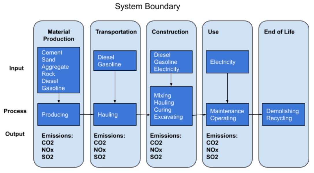
Figure 1. System boundary of a the life cycle stages of a rock-fill dam[1]
Subsystem of Rock-Filled dams: The components of a rock-fill dam are simple in comparison with other types of dams, and the majority of the materials used are borrowed from the surrounding area of the dam therefore making it an environmentally friendly choice for a dam construction.
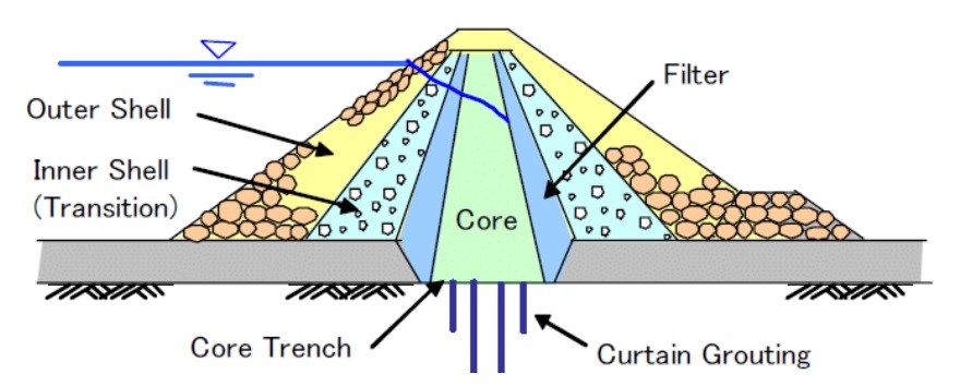
Figure 2. Components of a rock-fill dam [2]
The subsystem chosen for the life cycle analysis is the core of the dam, the core of the dam can be constructed with either clay, reinforced concrete or asphaltic concrete.
Table 1 shows different materials chosen for the design of the rock-fill dam
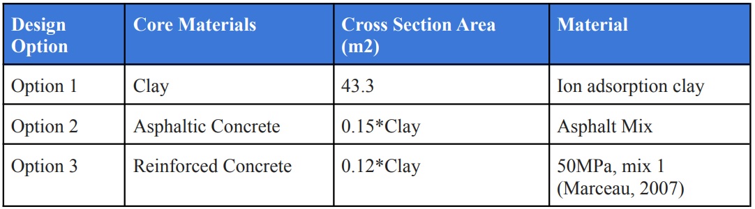
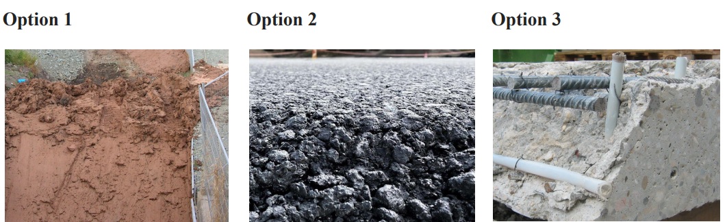
Table 2. Shows composition of materials used in the manufacturing different cores for a rock-fill dam
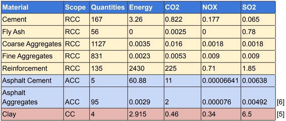
After gathering the necessary data to calculate the emissions of CO2, NOx and SO2, and the energy consumption for each material, the amount of emissions were calculated based on the volume of the different design options, the materials used as well as the number of interventions and maintenance that was needed. The volume of the design options are not identical, because each material offers different values of strength and durability.
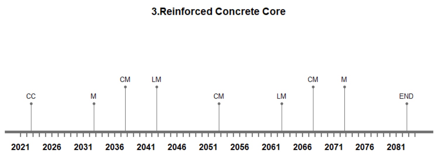
Life cycle timelines of different cores: When it comes to maintenance of the core of a rock-fill dam, there are two failures that need to be kept in check, crack maintenance and leakage failure. The lifespan of a rock-fill dam is 60 years[3]. The maintenance and interventions are assumed based on the fact that clay cores have more failure rates and show more sensitivity to weather conditions, both during construction time and performance time, on the other hand asphaltic concrete cores have lower failure rates and are not affected by weather conditions during the period of construction. Reinforced concrete is assumed to be more durable in terms of cracking and leakage compared to the design option of clay core[4].
Table 3. Interventions for the different design options
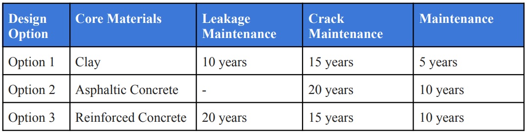
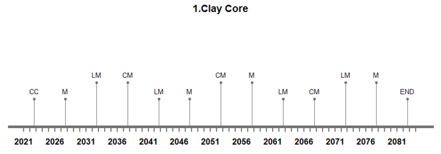
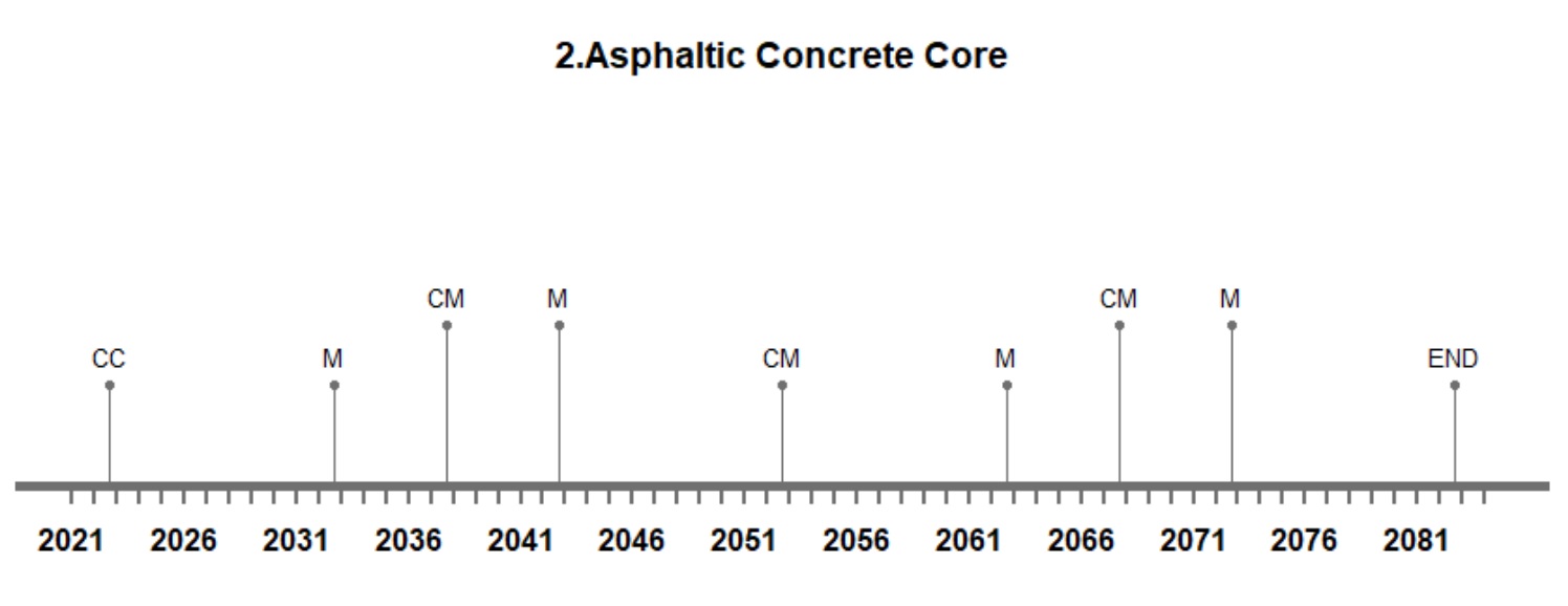
The construction of the core of a rock-fill dam with Asphaltic concrete and reinforced concrete requires less maintenance in comparison with clay core. Even though the construction of the clay core might cost less during the initial stage, the maintenance throughout the service life of the dam increases the cost and emissions associated with the dam.
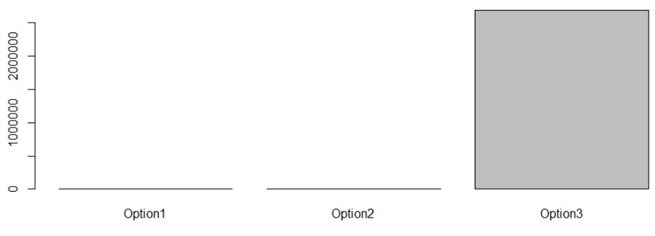
Figure 3. Energy level consumption for different design options.
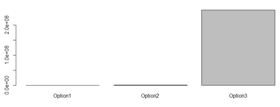
Figure 4. CO2 emissions for different design options
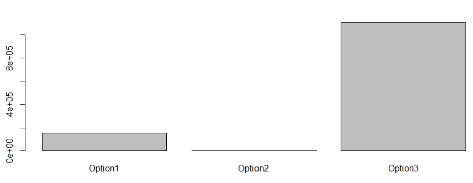
Figure 5. NOx emissions for different design options
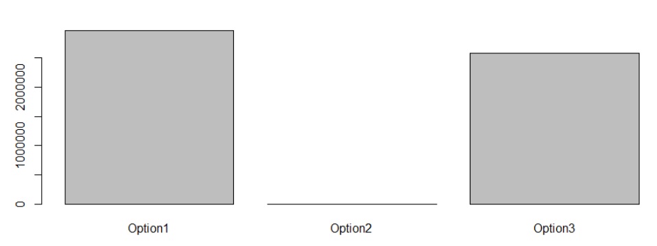
Figure 6. SO2 emissions for different design options
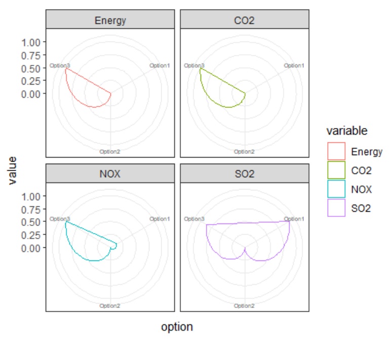
Figure 7. Radar plot of performance indicators
If we look at the results of the bar graphs illustrating the energy consumptions and the emissions of the different design options, we can see that each option leaves different levels of footprint. What seems to be a common pattern is that option 3 for the core which was designed with reinforced concrete seems to have the highest value in all three aspects of Energy, CO2 and NOx, but if we look at the results of the SO2, we can see that option 1 which was designed with clay, has the highest emissions of SO2. Considering that clay has a higher probability of leakage failure in comparison with reinforced concrete, as well as considering the higher frequency of interventions needed for the clay core, option 1 can’t be favored over option 3.
However, seeing that option 2: Asphaltic concrete core, has a significantly lower probability of leakage failure and needs a lower frequency of interventions throughout the service life of the dam, combined with the low emissions and energy consumptions, option 2 can be favored over the other options.
MCDM – Analytic hierarchy process (AHP)
In order to make the decision about the design options, multiple criteria need to be assessed in order to choose the most suitable combination of materials and dimensions. Based on the results from the emissions and energy consumptions, different numbers of priority are given to the design options, the numbers are given based on the 1-9 Saaty’s scale (Saaty, 1980):
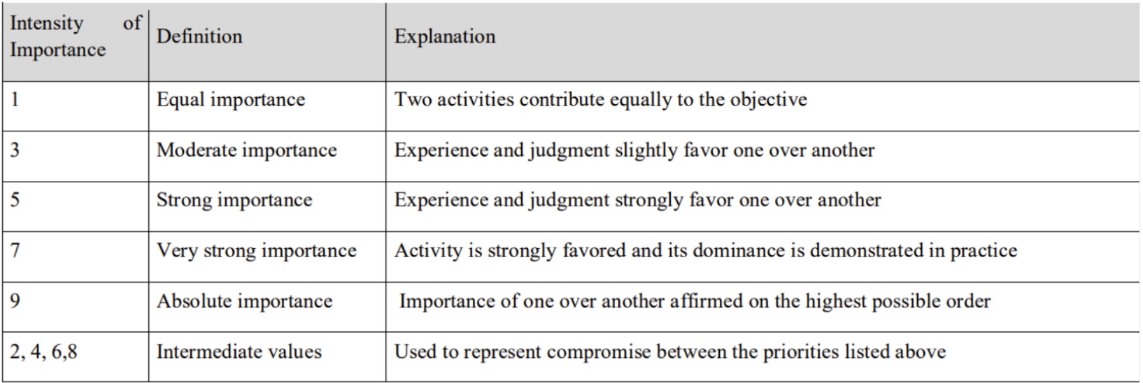
The different levels of importance are given separately to each option based on different criteria of emission and energy consumptions after considering the results from the bar plots.
Table 4. The results of the Analytic Hierarchy Process operation is listed in the table below
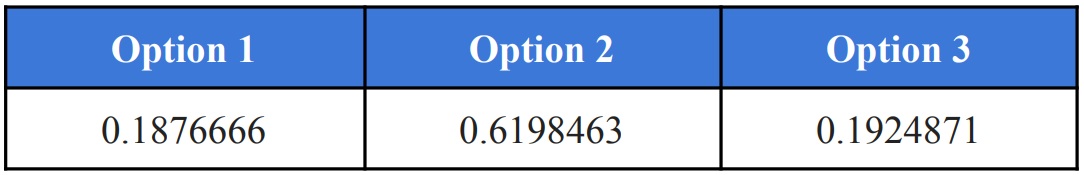
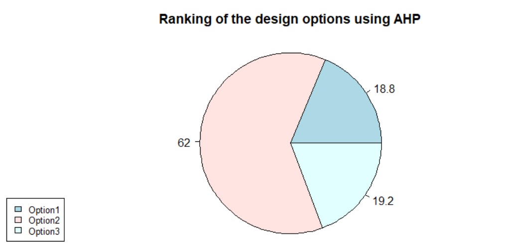
Evidently from the results of the AHP we can see that option 2 is favored because of the significant difference in level of energy consumptions and low levels of emissions. For this method of decision making, the significance was given based on the results of the bar plots.
MCDA – TOPSIS
Technique for Order of Preference by Similarity to Ideal Solution (TOPSIS) is performed on the different design options in order to find the ideal solution by giving weight based on the importance of each criteria. For this decision making tool Energy is given the highest priority because it has the highest value of consumption and is related to emissions in indirect ways. The design options are ranked based on the results of the TOPSIS analysis.

Because of the low number of interventions, the low level of energy consumption and emissions, option 2: Asphaltic Concrete Core for the construction of a rockfill-dam is considered to be ideal. These methods of decision making took into account the footprint of the materials used for the construction of the core. By also taking the fact into consideration that asphaltic concrete can be produced faster and is independent of weather conditions, we can see that it is fit to be the ideal solution for the design of the structure. Another factor that should be mentioned is the self-healing properties of asphaltic concrete that decreases the need for interventions and reduces chances of leakage failure[4].
Conclusion:
Rock-fill dams promise better environmental performance and have lower emissions in comparison with other types of dams, this is largely due to the fact that the majority of the material used for the structure can be borrowed from the vicinity of the dam[1]. The downside of rock-fill dams is the statistically high number of failures. In order to combat the high rate of failure, while at the same time keeping the performance advantages, we need to consider design options that make the structure more sturdy and less likely prone to failures.
The design of the core of the rock-fill dam provides significant strength against leakage and other types of failure, and the materials used in the design of the core play a vital role in keeping the structural part against these types of failures that the dam faces.
The core of a rock-fill dam can be created from Clay, Asphaltic Concrete and Reinforced-concrete. Each design option has its own arguments in terms of benefits and drawbacks, in order to choose the ideal solution for the design of the dam, the options have to be assessed in a multifaceted process.
After considering the volume of each design option, as well as the rate of interventions and the consumption of energy as well as the emissions caused by each type of material, the design options were weighed against each other in multiple criteria decision analysis. The main focus of this multi criteria decision analysis was on the energy consumption and the emissions. The purpose is to find the design option that has the least consumptions of energy.
The results show that if the rock-fill dam is designed with an asphaltic concrete core, then the least amount of energy will be used as well as the lowest amount of emissions will take place. Aside from these results, it can also be seen that during the lifetime of the rock-fill dam, the asphaltic concrete core needs the least amount of interventions and maintenance due to the self-healing properties of asphaltic concrete and low probability of leakage failure[4]
References:
[1] Liu, C., Ahn, C. R., An, X., & Lee, S. (2013). Life-cycle assessment of concrete dam construction: comparison of environmental impact of rock-filled and conventional concrete. Journal of construction engineering and management, 139(12), A4013009.
[2] Krikar, M., & Noori, G. (2013). Numerical analysis of earth dam seepage problems” (Doctoral dissertation, Master Thesis, University of Nottingham).
[3] Fu, X., Gu, C. S., Su, H. Z., & Qin, X. N. (2018). Risk analysis of earth-rock dam failures based on fuzzy event tree method. International journal of environmental research and public health, 15(5), 886.
[4] Alemie, N. A., Wosenie, M. D., Belew, A. Z., Kibret, E. A., & Ayele, W. T. (2021). Performance evaluation of asphalt concrete core earth-rock fill dam relative to clay core earth-rock fill dam in the case of Megech Dam, Ethiopia. Arabian Journal of Geosciences, 14(24), 2712.
[5] Vahidi, E., Navarro, J., & Zhao, F. (2016). An initial life cycle assessment of rare earth oxides production from ion-adsorption clays. Resources, Conservation and Recycling, 113, 1-11.
[6] Marceau, M., Nisbet, M.A. and Van Geem, M.G., 2007. Life cycle inventory of portland cement concrete. Portland Cement Association.