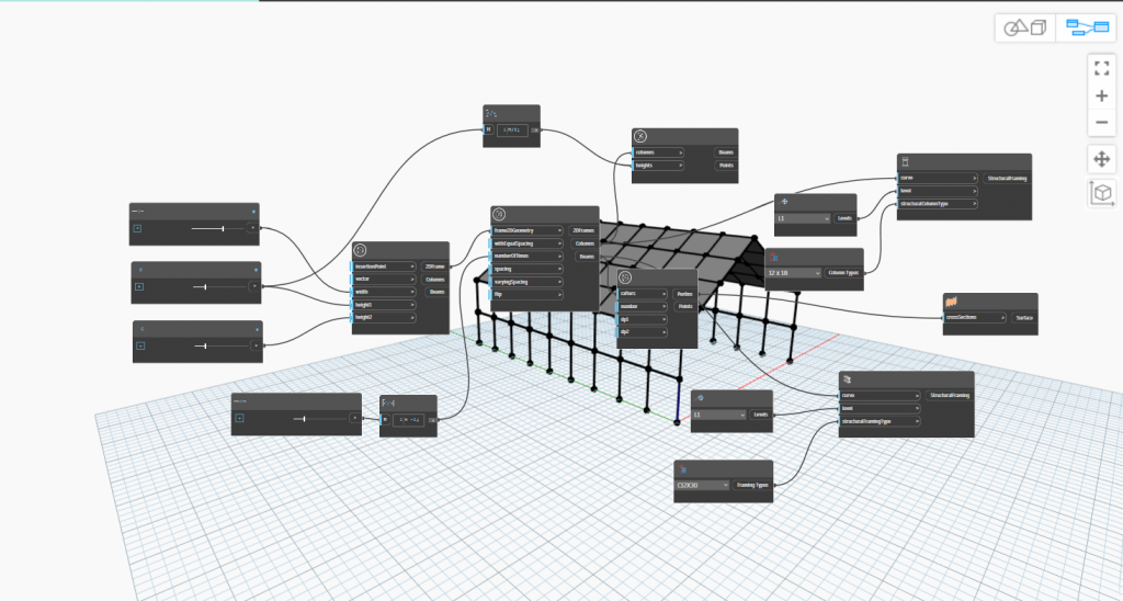
The System chosen is a Steel Frame Structure, while the component of which the parametric model is made upon is the Beam-to-Column Connection, which is introduced with detail in this page. Nevertheless, another simple frame parametric model was created in order to effectively integrate the Steel Frame Structure into the holistic Harbor Facilities System.

Access the Simple Frame Parametric model → simple frame model
Beam-to-Column End Plate Connection Parametric Model
Introduction
The domain we are focusing on is Moment resisting Frames, this is done to with the goal of supporting the structural analysis into a more cost-effective plate design.
The selected model is a model of a connection between two steel members in a moment-resisting frame. For our model an end plate is chosen, which connects the beam and the column through a plate bolted to the column and welded to the beam. An example of a simple application is in a simple steel frame in an industrial one-span structure, the slenderness of the structure makes it vulnerable to lateral forces such as wind and earthquake forces in one direction and more resistant in the other.
Parameters controlling the model
Steel frame connections vary according to the type of elements they connect such as beam-to-column, column-to-column or beam-to-beam connection. Their types differ according to the type of rigidity used in the analysis.
The selected parameters for the connection model are:
- Bolt diameter (db) and bolt hole diameter (do)
- Bolt spacing (e , p1 , p2)
- Total stress area of the bole
- Thickness of the end plate tep ≥ 4× db
- Bolt arrangement (number of columns)
- Plate’s width and depth Width = 2e + p1 * (n-1) , Depth = 2e + p2 * (n-1)
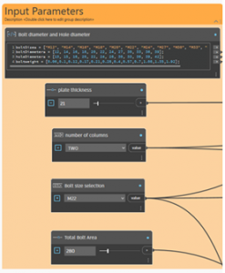
Figure.1 demonstrates the input nodes used in DynamoBIM.
- Purpose of the parameters
Bolts, as connecting members, their diameters impact the tensile capacity and the shear strength of the connection. Its diameter is calculated according to the tensile capacity, shear capacity and Bearing resistance [1]. Following to this the bolts diameter are determined which creates the final arrangement of the bolts on the plate, of which both their number and the spacing between them is calculated.
Bolt spacing must ensure adequate load distribution and prevent failure modes, and it is determined to satisfy conditions considering the bolt’s diameter and the thickness of the attached elements [1].
The minimum distance for the end distance is e = 1.2 do and the minimum spacing between bolts is p1 = 2.2 do horizontally, and p2 = 2.4 do vertically. The Thickness of the end plate provides support against bending or deformation of the column, and its minimum limit is determined according to the previously mentioned formula tep ≥ 0.4× db.
The determination of the spacing between bolts results in calculating the width and the height of the end plate. This is done after calculating the number and properties of the connecting bolts that will resist the applied forces.
Width = 2e + p1 * (n-1)
Depth = 2e + p2 * (n-1)
While the bolts should be arranged symmetrically, and it is a parameter that changes the lever arm, an input parameter is established to limit the positioning of bolts to an even number of 2,4 or 6 bolts for each column, which in turn determines the orientation of the plate. In addition to this, the number of needed bolts is rounded up to the nearest even integer also to ensure having a real number of bolts and a symmetrical distribution of the bolts.

High-performance criteria
Although complex Moment-resisting connections offer un-obstructed bays, unlike braces, they are usually complex and more expensive [2]. Those issues are addressed in the form of a high-performance criteria as follows:
- Number of bolts
- Weight of the connection
The resulted model will consist of the end plate with the distribution of bolts according to the minimum spacing between bolts and with an indication showing the minimum accepted thickness. Nevertheless, other factors play role in determining the thickness of the plate thereby it will be an input data determined by the designer. Each input parameter is defined and preset according to the following values in order to constrain the input values of the in input-nodes
| Input Parameter | Unit | Min. Value | Max. Value |
| Bolt net area | mm2 | 100 | 1000 |
| Number of Bolts | - | 4 | 16 |
| Plate thickness | mm | tep ≥ 0.4× db. | 200 |
| Number of columns | - | 2 | 6 |
In the table below is a sample of bolt types with their diameter and the associated normal round hole diameter both in mm according to “EN 1993-1-8:2005 Section 3.8” [3]
| Size | M12 | M14 | M16 | M18 | M20 | M22 | M24 | M27 | M30 | M33 | M36 | M39 |
| db | 12 | 14 | 16 | 18 | 20 | 22 | 24 | 27 | 30 | 33 | 36 | 39 |
| do | 13 | 15 | 18 | 20 | 22 | 24 | 26 | 30 | 33 | 36 | 39 | 42 |
| Avg. weigt | 0.06 | 0.1 | 0.12 | 0.17 | 0.21 | 0.28 | 0.4 | 0.57 | 0.7 | 1.08 | 1.35 | 1.92 |
Those parameters will assure a minimal case of design in regards to the number of bolts and the connection weight, which subsequently influences the complexity and cost of the designed plate. The weight of both the plate and bolts vary according to the type of bolts and steel used for the plate. An input of steel type and density for both the bolts and the plate gives us the desired results of the connection weight and therefore its cost.

Model evaluation, extremes and limits
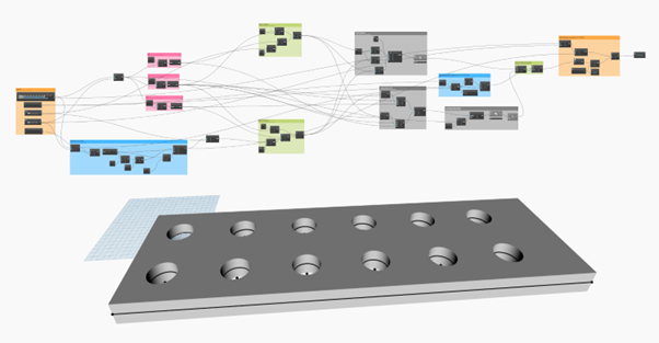
The model, depicted in Figure.2, creates a tool that calculates the minimal need of bolts and distributes it according the Eurocode guidelines, resulting in a symmetrical distribution of bolts on the desired plate. Nevertheless, this design does not take into account the placement of the welded beam on the plate, which can not be occupied with bolts. A solution for this is to include an input variable of various steel cross-sections that is located in the center of the plate, then identifying the available area for locating the bolts, and adjusting the plate’s dimensions accordingly.
Another issue with the model is that it creates the grid of the needed bolts starting from the lower corner of the plate with an offset of the x and y axis that equals e (minimum edge spacing). The result is that it does not consider the remaining of the plate’s width and depth after rounding the quotient of the calculating process.
Regardless of the issues paired with the maturity of the model, an important point for boosting the model and improving the usability is to connect the model to a database that carries sensible and usable amount of bolt and plate properties which gives the model its functionality in real world situations. In addition, implementation such model into a machine learning model can take part in various applications one of which is the evaluation of structural design in the terms of cost-efficiency or inspecting the seismic-resisting properties of joints in old structures.
Alternatives and engineering aspects
With the presence and development of object-specific and unspecific programs that with the ease of a button creates a high level of detail joint design, the simplicity of the model creates a computationally light tool that can greatly ease the primitive design phase and help guiding a cost-effective decision-making process.
Alternatives for calculating the code requirements of a design such as a joint design have existed a very long time ago with basic tools such as excel sheets. For some cases that can come in handy, but as simple as this solution seems it does not add much value to the design process and such example lacks the creative space that a geometrical model can provide to enable innovative breakthroughs.
On the contrary, Automative product development sought its way into becoming an essential part of the design and production of structural elements [4], this comes in parallel with the increasing complexity of structures along with the risks and requirements associated. Although using multi-objective tools require high computational power, they are capable of efficiently conducting monotonous tasks and calculations allowing more focus on the innovation of solutions suitable with the increasing complexity of today’s issues.
[1] Standard, British. “Eurocode 3—Design of steel structures—.” BS EN 1, no. 1 (1993): 2005.
[2] Boracchini, Alfredo. Design and analysis of connections in steel structures: fundamentals and examples. John Wiley & Sons, 2018.
[3] EurocodeApplied.com (n.d.) Bolt design properties according to Eurocode 3. Available at: https://eurocodeapplied.com/design/en1993/bolt-design-properties (Accessed: 10 January 2025).
[4] Güngör, A., 2006. Evaluation of connection types in design for disassembly (DFD) using analytic network process. Computers & Industrial Engineering, 50(1-2), pp.35-54.
Main Page I Introduction I Individual Systems I Integrated Ontology I Integrated Parametric Model