Building dams for traffic roads is one of the oldest construction methods, which was already used in pre-Christian times, for example, by the Romans and the Chinese. In traffic construction, dams are built where otherwise no even routing would be possible due to depressions in the terrain. Those Dams are earthworks that use soil as a building material, which is why their inherent strength and stability is significantly lower compared to materials such as steel or concrete. Strictly speaking, the actual dam is only a part of the entire building structure. Nevertheless, the term dam is used in the following for the entire structure and the actual earthwork is referred to as the dam body. The main task of the dam body is to safely transfer the traffic loads into the adjacent subsoil. [ENG a. AL-A 2012, KEI 1954]
In Germany, the design standards for road dams are the ZTVE-StB 94 [1] and the ZTVA-StB 97 [2] and the standard for railway dams is the Ril 836 [3]. The components of the superstructure differ depending on the function. For railway dams, a further distinction is made according to the type of track structure: ballasted and slab track. The first component at the top of the dam is the track structure or the road surface and for ballasted tracks another part of the superstructure is the ballast that lays underneath the track structure. The bottom part of the superstructure of traffic dams are the bases courses. According to [3] for railway dams there are base courses (frost protection layers, base courses with or without binder and asphalt base courses) that are part of the superstructure and protective layers that are part of the Substructure or are counted as a separate dam component. Since those protective layers are used for load distribution and frost protection they will be equated with base courses. The upper layer of the substructure is an improved or consolidated dam layer, and the main part of the substructure is the dam body. The loads acting on the dam as well as its dead load are transferred into the natural subgrade via the foundation. [1, 3, ENG & AL-A 2012, GÖB & LIE 2004, SCH & RUM 2009] Figure 1 shows a rough system sketch of the whole traffic dam structure.
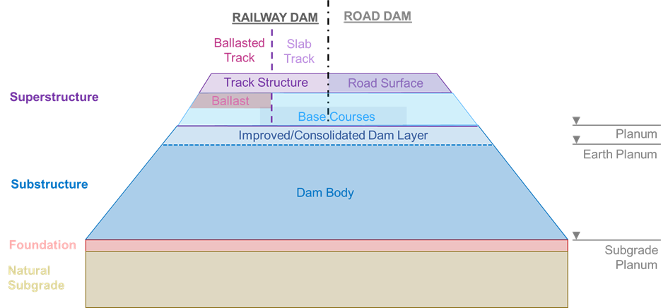
Figure 1 System sketch of the components of a Traffic Dam [Own Illustration]
The earth body is made in a trapezoidal shape, as this gives the soil the greatest stability and at the same time uses the least amount of material [KEI 1954]. The design-relevant geometrical parameters of the dam body are shown in the Parametric Model part in Figure 4. The side slope defines the inclination between the dam base and the dam shoulder which plays a very important role in the stability of the earthwork and depends on the soil material used. The cross slope defines the inclination between the dam shoulder and the crest point, i.e. the planum inclination. This factor depends on the requirements of the respective guidelines for railway and road use. [GÖB & LIE 2004]
Ontology Model
The .owl file for the ontology can be found here.
What is the purpose?
To get first rough specifications for the design of a dam, especially its earth body, depending on the available material and use.
What is the scope?
This ontology includes classes such as dam physical components, possible materials, and possible uses and their relations plus Individuals.
Who are the intended users?
The intended users are engineers that have to design dams for infrastructure according to the german standards.
What is the intended use?
The intended use is the sharing of information by engineers, geologists and rock mechanics experts.
Boundary Conditions
Since an ontology is only a model of reality the boundary conditions must be defined. In the ontology, the design of the foundation and the interaction with the subsoil shall be neglected. The main focus of the design is on the earth body of the dam, which is to be constructed as a new building. A homogeneous dam consisting of a uniform soil material is assumed and the use of permissible foreign material such as slag or recycled construction materials is neglected. In addition, the groundwater conditions must be simple and the subsoil must be stable. The dam base is assumed to be straight, which theoretically varies depending on the topography. In general, only a cross section of a straight route is considered neglecting the length of the dam as well as terrain and alignment conditions. [DAC & DAC 2017, ENG & AL-A 2012, KEI 1954]
Ontology
The design of a traffic dam is highly dependent on its use since there are different standards for road dams and for railway dams. Therefore, the class “Use” is a direct subclass of the “TrafficDam”. The subclass “TrafficLoadClassification” includes the planning relevant load classes for road dams and route categories for railway dams according to their standards. In this ontology, the material for traffic dams is limited to granular soil material and is added through “EarthFillMaterial” that is a sibling class of the already mentioned classes. Since fine-grained soils are not suitable for homogeneous dam bodies [GÖB & LIE 2004], this class contains only coarse-grained, mixed-grained and fine-grained soils. The individuals of those subclasses were chosen randomly and are classified according to DIN 18196 [4] as the side slope angle of the dam depends on this soil classification. Their data properties are the specific weight and the proctor density, which are important for the verification guidance and the specified degree of compaction of the dam layers, and are experience values from [SOO & ENG 2008, p. 124f.]. (Compare Figure 2)
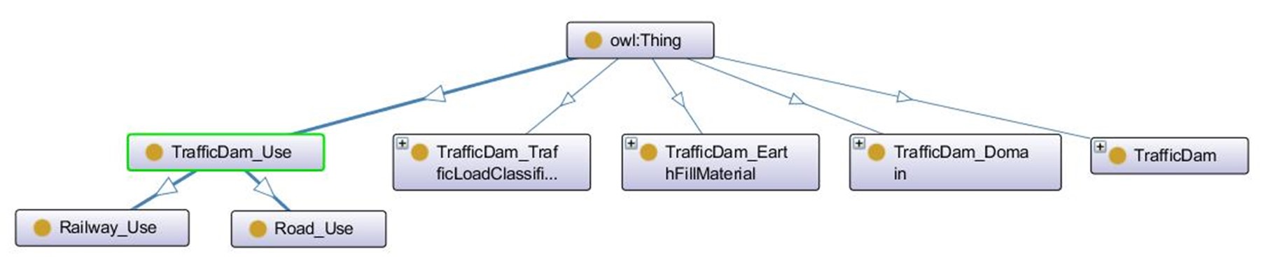
Figure 2 Main classes of the Traffic Dam Ontology [Illustration from OntoGraf – Protégé]
The class “Domain” describes the components of the super- and the substructure of the traffic dam system. The combination of the components depends on the use of the dam and for railway dams of the track system. Those connections are also implemented in the “Traffic Dam”-class since they are the basis for the design of the traffic dam as they influence the object and data properties of the design options (Compare Figure 3). According to ZTVE-StB-94, the layers above the planum are referred to as base courses (Tragschichten) and are included in the Superstructure. Ril 836 defines an additional earth planum and assigns protective layers (Schutzschichten) between planum and earth planum, wich are part of the Substructure or are counted as a separate component. Base courses can include frost protection layers (Frostschutzschichten), base courses with or without binder (Tragschichten mit o. ohne Bindemittel) and asphalt base courses. According to Ril 836, protective layers are used for load distribution and frost protection, which is why they will be equated with base courses [1, 3].
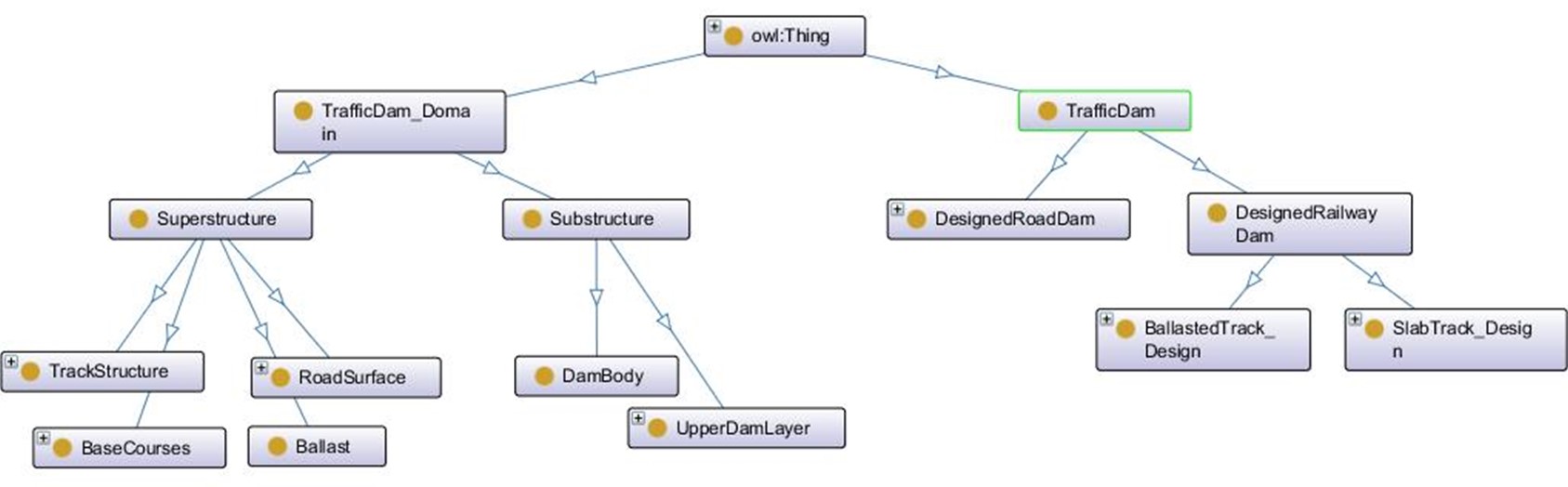
Figure 3 Structure of the “Domain”- and “Traffic Dam”-classes for the components and the design of the Traffic Dam [Illustration from OntoGraf – Protégé]
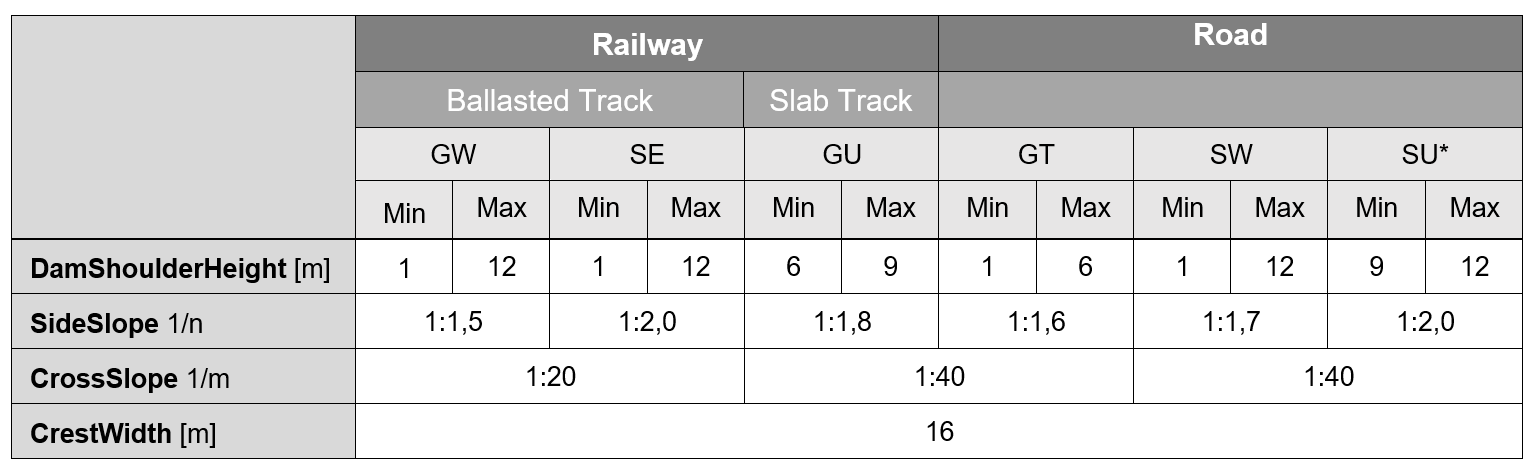
Table 1 shows the examples with the geometrical properties prepared for the design, which are passed to the ontology as Individuals. There is a minimum and a maximum version of each design option, which represent limit values. The minimum and maximum values of the dam heights as well as the side slope are based on [3, 836.0506, p. 2]. The values for the cross slope were taken from the respective standards [FLO 2006, GÖB & LIE 2004]. A uniform length of 16 m was selected as crest width for all Individuals that was oriented towards the new construction of double-track lines in rail traffic for design speeds below 300 km/h [GÖB & LIE 2004].
Table 1 Individuals for the Design Classes of “TrafficDam” [Own Illustration]
Outlook
The developed ontology could be completed with further examples as well as more detailed information about the superstructure and an expansion of the relations between superstructure and substructure. It can also be extended in many ways: On the one hand by removing parts of the mentioned boundary conditions and on the other hand if environmental interfaces with other models were captured and implemented. The selected system has a strong interaction with the foundation and the subsoil, which should be integrated. Especially for the economic efficiency of the construction project, it is also important to consider the excavation and transport of the dam material to be used. Furthermore, the compaction methods for the dam construction can be determined depending on the soil class as a further extension. The ontology created can also be used as a starting point for the design of traffic dams in other countries where different standards apply. Another interaction that is important for the economic efficiency of a dam construction would be the inclusion of a bridge model. Depending on the project, the construction of a bridge may be more economical than that of a dam, depending on parameters such as the topology as well as length and routing of the planned railway or road.
Parametric Model
The .dyn file for the parametric model can be found here.
You could also download the whole zip here.
With the preliminary work of the ontology, a parametric model of the traffic dam can be elaborated.
Design Challenge
The purpose and scope of the tram dam system serves as the starting basis for the design challenge of the parametric model. For this model the distinguishing between road and railway dams is no longer practical since the use of the dam is already defined at the beginning of the design challenge in a construction project to be planned. A railway dam was chosen because enough information was already available for its simplified design through previous research, especially with the Ril 836 [3]. For the model in Dynamo BIM, the geometry of the dam is created by connecting the vertices of the dam body. The relevant geometrical parameters for the description of the location of these vertices are shown in Figure 4.
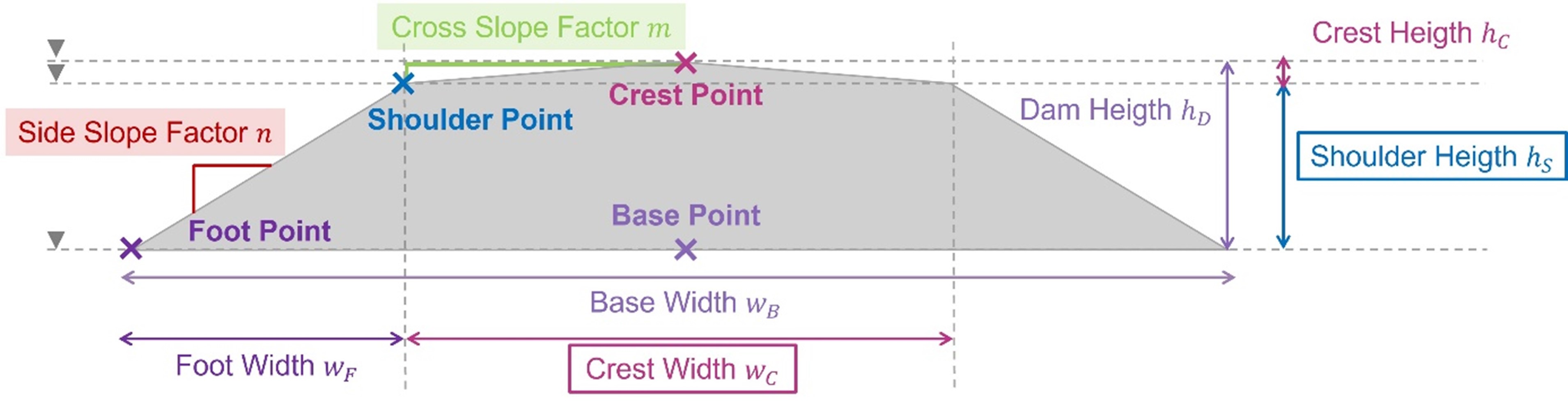
Figure 4 Geometrical Parameters for the Dynamo-Model of a Railway Dam [Own Illustration]
The outlined parameters in the illustration are passed to the model as input parameters, while the highlighted parameters are passed internally within a node. The rest of the parameters are calculated within a node and can be output later. The shoulder height can be varied between 1 and 12 m, while the crest width is fixed at 16 m. The cross slope factor is a fixed value that depends on the type of track of the railway dam. However, the side slope factor changes with the shoulder height of the dam depending on the soil type used for the earth fill.
As different design options of a railway dam are to be compared later, criteria are needed to evaluate the suitability of a design. A first important factor is the costs incurred. Since the production costs that arise from the layer-by-layer compaction of the individual dam courses depend on the type of possible compaction methods and soil placement and are a rather complex issue, only the costs for the transport of the earth fill material are investigated. As with the choice of soil material, transport also depends strongly on possibly available excavation sites, which must be neglected in this model. However, the weight of the earth fill material required for the dam can give a simplified indication of the transport costs incurred, as trucks can only be loaded to certain tonnage specifications. The different storage densities of a soil in the truck are neglected. [compare DAC 2017a] The total dead weight of the dam material results from the volume of the dam and the soil dry density. In [3], there are different requirements for the compaction of the soil layers depending on the soil type and track system. A distinction is made between the upper dam part (planum course) near the earth formation, which often has to be compacted slightly stronger, and the lower regular dam part (regular course). This degree of compaction influences the dry density and specific weight of those dam parts and must be taken into account for the separate calculation of the dead weight, which is why a help geometry must be used in Dynamo (Figure 5).
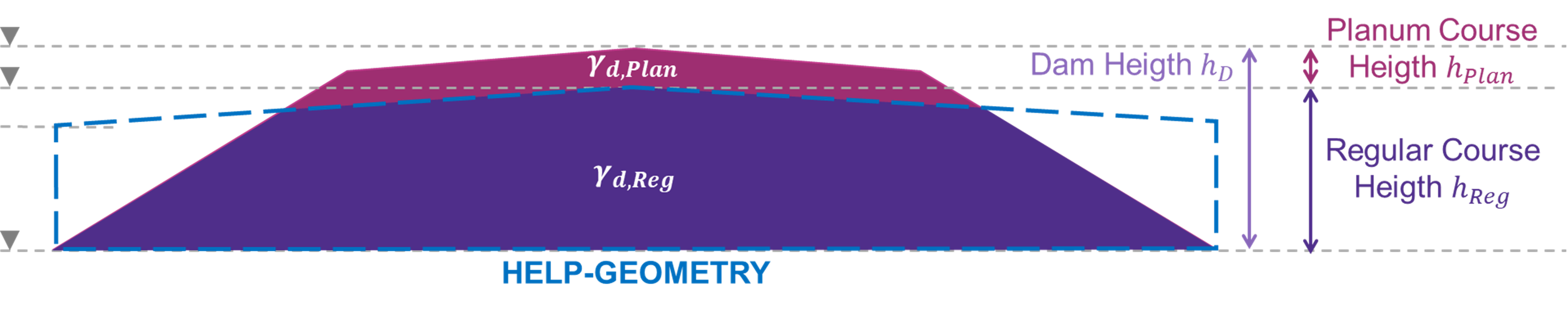
Figure 5 Geometry of the planum and the regular course dam parts with their different specific weights [Own Illustration]
An important factor in the design of a dam is the fulfilment of the soil mechanical verifications of the subsoil beneath the dam. With the side slope factors used from [3], the stability verification of the slope can be omitted under simplified conditions, which apply to this model [GÖB & LIE 2004]. For other verifications of stability, for example the foundation failure verification, the surcharge load of the dam acts like an inclined off-center load from one half of the dam [DAC 2017b]. The surcharge load from the dam is reflected by the vertical dead load of the dam, which is chosen as the second high performance criteria. The vertical dead load per meter length of the dam can be calculated by the product of the specific weight of the earth fill material and the volume of the dam divided by its overall-length. Non-numerical aspects such as aesthetics are not considered in this model. The geometry of the dam leaves no room for aesthetics, as it is purely functionally responsible for stability. An aesthetically pleasing design for dams can only be achieved through landscape planning [SCH & RUM 2009].
Modelling with Dynamo BIM
In Dynamo BIM three different custom nodes were implemented to allow the design of a railway dam with a ballasted track and an earth fill from a widely graded gravel-silt mixture (GU). The “DamRouteDesign”-Custom Node outputs the local coordinate system of the dam with its origin in the dam base point and the curve of the dam routing. The input parameters specify the routing of the dam as well as its position in the global coordinate system. In this way, the route could be adapted to a topography that could be implemented as an additional model in the program. The dam route is only a simplified demonstration of a route but would have to be considered in more detail for a standard-compliant design. The “DamCrossSectionDesign”-Custom node receives the local coordinate system from the first node and creates the cross section of the dam in the XY-plane of the coordinate system with the help of the desired shoulder height and the crest width of the dam. This node outputs the curve of the cross section, the location of the dam foot point and other geometrical parameters that are required for the third node. In addition, “Watch”-nodes can be used to display other planning-relevant quantities that may be helpful for planning a railway dam, e.g. to draw plans. The third custom node is called “DamBodyDesign” and models a solid by merging the route with the cross section of the dam. In addition to the planum course and the regular course part of the dam, the node also outputs further quantities that are relevant for soil mechanical calculations and planning to be carried out.
Design space and alternatives
The design space of this model allows only very minor changes to the system. Since the only component of the model is the dam body, changing or rearranging the system components to create design options is not possible. The variation in this simplified railway dam design is limited to changing the material, which changes the soil mechanical parameters on the one hand and the side slope factor on the other and to changing the track system of the superstructure. The choice between ballasted and slab track influences the cross slope factor. The design space allows the variation of the shoulder height, which influences the whole system through the side slope factor. Another adjustable factor is the proctor density of the earthfill material between the soil-specific limits. In reality, this parameter cannot be easily adjusted but is tied to the available soil material. However, the model can be used to test the influence of the proctor density on the high performance criteria. Table 2 shows the input parameters used for the three design alternatives (option 2-4) compared to the initial model (option 1). For every option an individual custom node for the cross section and the dam body of the railway dam is implemented (only few changes within the code).
Table 2 Input Parameters for a Railway Dam of Design Option 1 – 4 [Own Illustration]
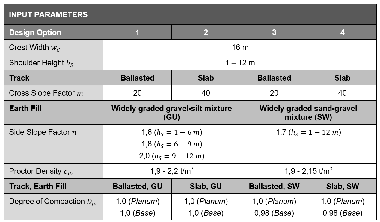
Some of the input parameters are the input for all the four design variations so their performance can be compared and assessed. Therefore, the routing of the dam is the same for all design options as well as the crest width, which was assumed to be 16 m for route category P300. The shoulder height of the dam can be selected between 1 and 12 m and influences all four design variants. By translating the local coordinate system, all four railway dam options can be compared side by side. Figure 6 shows an example of the direct comparison of the high performance criteria for the four design options. The figures show that the choice of track system has a much smaller influence than the choice of the earthfill material for those options. The difference between the values may seem very small but especially the variance of total dead weight might allow a way more economical design of a railway dam.
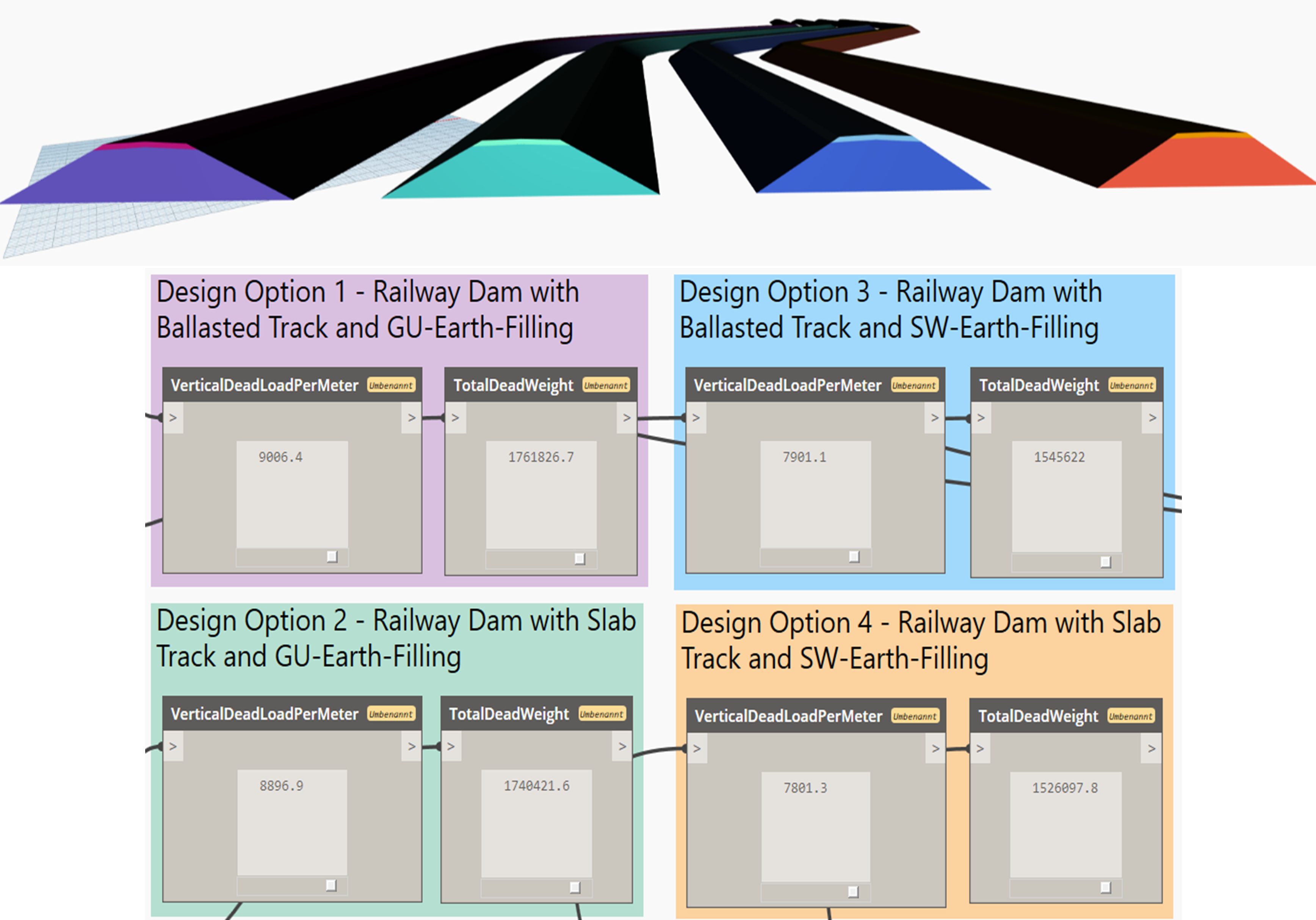
Figure 6 Comparison of the Dam Bodies from the four implemented Design Options (Shoulder Heigth 12 m, Proctor Density for GU and SW 1,9 t/m3) [Own Illustration]
Outlook
The model would be very easy to extend with more design options using the custom nodes. Working on the simple geometric model gave a good overview of the functions and possibilities of the program Dynamo BIM. The model can be extended with more detailed information or more components like the superstructure to become closer to reality.
References
[1] ZTVE-StB 94: Zusätzliche Technische Vertragsbedingungen und Richtlinien für Erdarbeiten im Straßenbau. Bundesministerium für Verkehr, Abteilung Straßenbau. 1994.
[2] ZTVA-StB 97: Zusätzliche Technische Vertragsbedingungen und Richtlinien für Aufgrabungen in Verkehrsflächen. Forschungsgesellschaft für Straßen- und Verkehrswesen e.V.: Köln, Arbeitsausschuß Kommunaler Straßenbau. 1997.
[3] Richtlinie 836 (Ril 836): Erdbauwerke planen, bauen und instand halten. Publisher: DB Netz AG, Deutsche Bahn Gruppe. 1999.
[4] DIN 18196:2006-06: Erd- und Grundbau – Bodenklassifikation für bautechnische Zwecke. 2006.
[DAC & DAC 2017] DACHROTH, W. and DACHROTH, T. (2017): 12 Bau von Verkehrswegen. In: Handbuch der Baugeologie und Geotechnik. Publisher: Dachroth, W. Springer Spektrum: Berlin, Heidelberg.
[DAC 2017a] DACHROTH, W. (2017): 8 Erdbau – Bauen in und mit Erde. In: Handbuch der Baugeologie und Geotechnik. Publisher: Dachroth, W. Springer Spektrum: Berlin, Heidelberg, p. 361 – 391
[DAC 2017b] DACHROTH, W. (2017): 9 Standfestigkeit und Sicherung von Erdbauwerken. In: Handbuch der Baugeologie und Geotechnik. Publisher: Dachroth, W. Springer Spektrum: Berlin, Heidelberg, p. 393 – 407
[ENG & AL-A 2012] ENGEL, J. and AL-AKEL, S. (2012): 9 Grundlagen des konstruktiven Erdbaus. In: Einführung in den Grund-, Erd- und Dammbau – Konstruktion, Bauverfahren, Nachweise. Carl Hanser Verlag GmbH & Co. KG, p. 215 – 241.
[FLO 2006] FLOSS, R. (2006): Handbuch ZTVE – Kommentar mit Kompendium Erd- und Felsbau. 3. Edition, Kirschbaum Verlag GmbH: Bonn.
[GÖB & LIE 2004] GÖBEL, C. and LIEBERENZ, K. (2004): Handbuch Erdbauwerke der Bahnen. 1. Edition, Eurailpress – Tetzlaff Hestra GmbH & Co. KG: Hamburg.
[KEI 1954] KEIL, K. (1954): Der Dammbau: Grundlagen und Geotechnik der Stau- und Verkehrsdämme. 2. Edition, Springer Verlag: Berlin, Göttingen, Heidelberg.
[SCH & RUM 2009] SCHMIDT, H.-H. and RUMPELT, T. (2009): 2.1 Erdbau. In: GRUNDBAU-TASCHENBUCH – Teil 2: Geotechnische Verfahren. Publisher: Witt, K. J. 7. Edition, Ernst & Sohn – Verlag für Architektur und technische Wissenschaften GmbH & Co. KG: Berlin, p. 1 – 97.
[SOO & ENG 2008] VON SOOS, P. and ENGEL, J. (2008): 1.3 Eigenschaften von Boden und Fels – ihre Ermittlung im Labor. In: GRUNDBAU-TASCHENBUCH – Teil 1: Geotechnische Grundlagen. Publisher: Witt, K. J. 7. Edition, Ernst & Sohn – Verlag für Architektur und technische Wissenschaften GmbH & Co. KG: Berlin, p. 123 – 125.