How does a Solar Power Tower Plant work?
A Solar Power Tower Plant (SPTP) represent a sustainable power plant using solar energy as its input to generate electricity. It consists of a high tower with a concentration point, the receiver, at its top. The tower is situated in the centre of a so-called Heliostat Field, comprising a huge number of Heliostats in a circular or semi-circular arrangement around the Tower. A Heliostat is a flat or curved, moveable mirror, which concentrates and amplifies the incident sunlight and reflects it to the receiver. As the sun moves throughout the day, the Heliostats have to track the sun’s pathway biaxially in order to increase their efficiency. By this, heat at temperatures of about 600 °C is developed in the inside of the receiver, which is absorbed by a Heat-Transfer-Medium (HTM) as water/ steam, air or molten salt.
This heat drives a conventional steam power plant, in which the transformation of thermal energy to electrical energy is intermediately done via mechanical energy. The different steps and necessary components of the Rankine cycle as one conventional cycle are shown in schema below. The surplus heat of the day can be stored in a warm reservoir by storing the heated HTM and thus, used at night to drive the conventional power block. So, the operation time of the SPTP is increased (s. Fig.1).
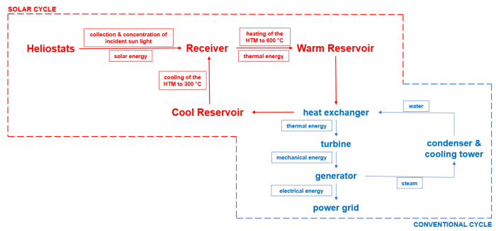
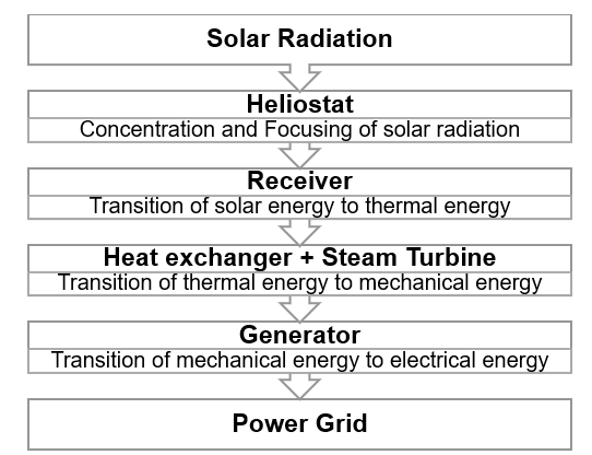
Fig.1: Working principle of the SPTP showing the components of the solar and conventional cycle [author’s diagrams]
Ontology of a Solar Power Tower Plant
What is the purpose?
The purpose of the following ontology is to break down the complex and sensitive system of a SPTP and give a basic understanding of its functional, physical and logical decomposition. With the help of the ontology, the designers get a good overview about the required components and their interaction as well as possible restrictions among these. The state-of-art for SPTPs is defined and serves as a basis for the designing process as well as for further improvements of the system.
What is the scope?
The following ontology focuses on the basic components of the solar cycle of the SPTP and their relations.
Who are the intended users?
The intended users of the ontology are the designers and engineers who take part in the designing process of a SPTP.
What is the intended use?
During the designing process, the ontology should be used as the basis for the development of a new SPTP with its best possible performance. This means to satisfy the demands for a high operation and cost efficiency, a simple and reproducible constructability, a high functional reliability as a well a good competitiveness, especially compared to other renewable energies as Photovoltaic Systems.
Development of an Ontology
Based on these key questions the ontology is developed in a bottom-up process. First, classes based especially on the physical decomposition of a SPTP are defined by grouping all the important components as well as their design variation into different class. While the subclasses provide the highest level of detail, the superclass stands for the general components of the SPTP. This results in a taxonomic hierarchy of the classes. All classes at the same level are disjoint to make sure that an instance of one class cannot be instance of another class. By this, the validation of the ontology remains reliable.
Based on this class hierarchy the object properties, or relationships between the classes, and their inverse are defined. Formally, “has” and the inverse “is … of” are added to the class names leading to an object property hierarchy. For each object property the domain and range are defined. While the domain describes the class that is related (input), the range describes the class which is related to (output). But the defined domain and range conditions do not represent constraints. Thus, property restricts have to be defined to express similarities, differences and limitations between the individuals of classes. For this ontology existential and at-most restrictions are used.
Instances are created with orientation towards already existing SPTPs. Thereby, it makes no sense of defining minimum and maximum limit values as with every new built solar power plant new technologies are applied leading to higher power capacities, greater collectors, total collector areas, etc. Thus, a new SPTP always exceeds the performance of the existing ones. For the creation of instances, the characteristics of three existing SPTPs serve as the basis. Some characteristics are modelled as data properties of the design option, but most define the data properties of instances. Due to a lack of reliable information some values are just assumption.
The resulting ontology is portrayed in the following Fig.2. As this ontology only represents a section of the real entity, it can be refined and extended with additional data depending on the current purpose.
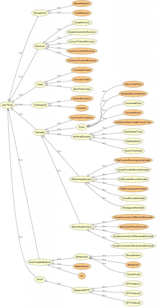
Fig.2: Representation of the resulting Ontology [taken from Protégé] 
Parametric Modell of a Solar Power Tower Plant
Goal and Scope
For the parametric modelling of a SPTP, the focus is only placed on the central tower with a receiver at its top (s. Fig. 1). As the receiver accounts for around 10 to 15 % of total investment costs, it is crucial to design the receiver carefully to increase the SPTP’s performance efficiency and reduce the energy generation costs. Although latter are also influenced by the design of the Heliostats, these will be neglected for this consideration as their physical embodiment depends on much more parameters than those defining the Heliostats geometry, and which require the usage of computer-aided design tools.
The goal is to create a parametric model of the tower and receiver of a SPTP within the software Dynamo Sandbox from Autodesk based on several geometric input parameters. These can be selected within a predefined range by the designers and engineers. The resulting model can be evaluated by several high-performance criteria to achieve the best design solution.
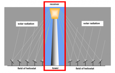
Fig.3: Design space for the parametric model of SPTP
Modelling of the Tower
The central tower is modelled as a tube by two solids based on an inner and outer circle and by subtracting the outer solid with the union of these two solids (DifferenceAll-node). It is defined by the three parameters of height, radius and thickness of the tower walls. According to JEBAMALAI (2016) the tower height is a function of the receiver’s thermal power and thus depending on the amount and arrangement of the Heliostats. But in literature no reliable model for the determination of the tower height based on the thermal power is available, so that for this model the height is freely selectable within a predefined range.
Modelling of the Receiver
For the modelling of the receiver a cylindrical external tubular receiver is chosen, which is the most widely used receiver type and applicable for the Heat Transfer Media (HTF) like molten salt, water/ steam and air. The receiver model consists of three different components:
- Horizontal Supply Pipes, where the warm HTF is transported to and temporarily stored
- Vertical Heat Exchanger Pipes, in which the HTF is heated by the concentrated incident sunlight of the heliostats
- Horizontal Collector Pipes, where the hot HTF is temporarily stored and either transported to the storage tanks or used to drive the conventional steam power plant
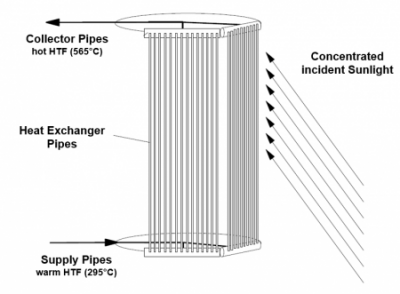
Fig.4: Scheme of a cylindrical external tubular receiver
All receiver pipes are modelled as tubes according to the same principle as the tower tube and defined by an outer radius and wall thickness. The curves of the supply/ collector pipes are based on the initial circle of the tower, which is translate along the z-axis to the top of the tower for the collector pipes and to the height “towerHeight – receiverHeight” for the supply pipes. For the heat Exchanger Pipes the same number of points at the curves for the supply and collector pipes are created in form of a list. The points at the upper curve represent the start point and are connected with the corresponding point at the lower curve by a line.
As an external tubular receiver is implemented, all pipes are located at the outer surface of the tower without any housing. For reasons of simplification other receiver shapes (conical or rectangular) are neglected and the receiver radius always equals the tower radius.
High Performanc Criteria of the Tower
The performance of the tower is evaluated by its material costs and the corresponding CO2-emissions for the material of steel and reinforced concrete. For this, the volume of the tower tube has to be calculated. As steel has a higher material strength than reinforced concrete less material is needed, which will be taken into account by the wall thickness of the tower tube. Thus, the wall thickness of the steel tower is reduced to one third of the wall thickness of the concrete tower resulting in two different tower volumes and by this in different material costs and CO2-emissions.
High Performance Criteria of the Receiver
Most of the decisions, taking during the iterative design process of a SPTP, are influenced by the required output of electrical power. Thus, the performance of the receiver should be measured by the generated thermal power at the receiver through the interaction of the incident sun rays and the Heliostats. But as the Heliostats are neglected for this consideration, the generated thermal power can’t be determined because a lot of required parameters depend on the characteristics and arrangement of the solar field and power block as well as on the optical quality of the Heliostats causing, or preventing, thermal losses.
Therefore, the performance of the receiver is evaluated by its aspect ratio (height to diameter), whether the defined input parameter of receiver height and radius are within the recommended range of 1 to 2. The ratio is calculated to reach the greatest possible efficiency of the receiver, and the resulting value is displayed by a Watch-node. Moreover, the compliance of the limit values is checked by Boolean operations and its result displayed by Watch-nodes. Here, the Boolean value “true” for both operations is desired. If one of the values is “false”, meaning that one of the limit values is passed, a new tower height is calculated based on the set receiver geometry, with which the limit values are maintained.
Sources
ALEXOPULOS, S. and HOFFSCHMIDT, B. (2017): Advances in solar tower technology. Publisher: John Wiley &Sons Ltd. WIREs Energy Environ, Vol. 6, Jan/ Feb 2017, p. 1 – 2.
BALZ, M. et al. (2019): Sun Sonne. Publisher: Schlaich, Bergmann und Partner Sonne GmbH: Berlin, eBook, 2019.
HIRSCH, T. et al. (2020): Erneuerbare Energien – Kapitel 11: Solarthermische Stromerzeugung. Publisher: M. Kaltschmitt, W. Streicher, A. Wiese, Springer Verlag GmbH: Germany, 6. edition, 2020, p. 995 – 1049.
JEBAMALAI, J. S. M. (2016): Receiver Design Methodology for Solar Tower Power Plants. Master Thesis, KTH School of Industrial Engineering and Management, Department of Energy Technology, Division of Heat and Power Technology: Stockholm, 2016.
See also other individual systems:
Or main topics: