Solving Incompatibilities
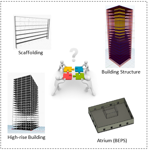
Fig1: Integration challenge combining 4 different systems
We combined the four different systems under a common renovation conceptual model that is able to evaluate alternative renovation processes in different buildings. The main challenge was to combine the 4 Dynamo models: two of them featuring multi-storey building construction, one for façade systems and their energy efficiency, and the scaffolding system for logistical planning. The use of Speckle did not fit our integration purpose and thus, we ve applied a step-by-step approach for the integration of our systems:
- Starting from the integration of the High rise Building & Building Structure which had many similarities.
- Connecting the scaffolding system in the outer side of the building for renovation purposes
- Re adapting the Building Energy Performance model to integrate it in the whole concept.
For the integration of the BEPS system in the combined parametric model, the initial atrium design system could not fit the purpose of the highrise building renovation. In fact, an atrium is used to provide more daylight in the center of the building when access from the sides is blocked; instead, in a highrise buildings, there is much daylight access, making the use of an atrium useless. To address this integration challenge, we designed a facade to evaluate alternative glazing ratio of the building. In the next figure 2, the geometry of the facade component is illustrated; the model is built with a focus on the integrated model, using length and floor height as common parameters, glazing ratio to regulate the solar access and thickness as insulation parameter.
Facade parameters:
- Building length
- Floor height
- Glazing ratio
- Insulation thickness
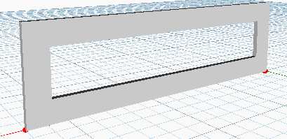
Fig 2: Facade model generation
Finally, in the next step, the new system is integrated in a single Dynamo script as is shown in Figure4 while Figure 3 illustrates the integration process in Dynamo, demonstrating the complexity during the integration process.
Integration in Dynamo
The first two systems which describe the building had many common parameters; they are both square in plan, both are systems of columns’ constructive grids and slabs (the first one has also a core), and both are oriented by the origin of the coordinate system. The main difference is their specification; the first one focused primarily on the dependencies between the static and geometrical aspects of the structure, whereas the second focused on the flexibility of the design spatially.
Due to the high level of similarity, it was rejected to integrate these two independently (by using both of them and joining some common points), but instead the one focused on the static aspects of the construction has been supplemented with the design options of the second one (such as changing the building’s general dimensions). And so, the primary structure of the building, including both its static and design parameters was complete.
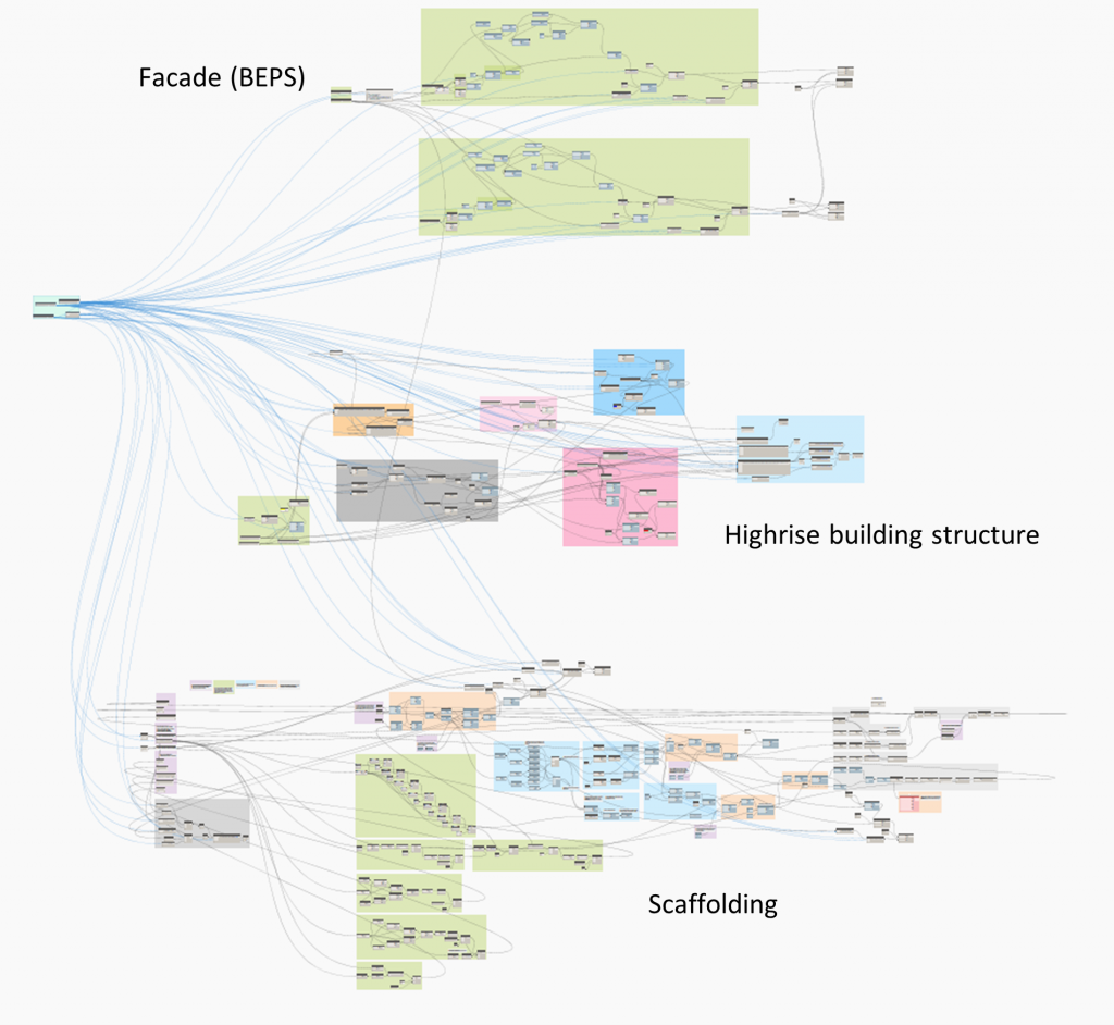 Fig 3: Integration process Dynamo scripting (Complexity illustration)
The building’s façade is a rectangular wall, described by two points (start and end), as well as height and thickness. This volume features a rectangular opening, whose dimensions can be scaled proportionally to the dimensions of the entire wall (in terms of percentage). The basic model is located with the start point of the wall in the origin. From there it is translated by half of the sum of building’s length and wall’s thickness by the axis X and again by the half of the length by the axis Y, which placed it on the destination. It has then been translated to all floors by the axis Z. This was furthermore copied by changing the XY-coordinated to the perpendicular walls. The view of all the façade geometries, which were not to be seen in the model (the in-between steps of the translation of the geometries) has been turned off (or had its ‘preview’ unchecked in Dynamo-speak). The common parameters with the building are here the length (which corresponds with the side’s length of the building) and height (being equal to the height of the one floor).
The way in which scaffolding is been attached to the building’s side is very similar to that of the façade, however in this case the independent flexibility was to some degree limited. This was due to the fact that the scaffolding is built of fixed modular components, each having 3m length, which means that the length of the scaffolding is not always equal to that of the building. The height of the scaffolding system has been however fully adjusted that of the building (both the height of the levels of the scaffolding, which fits the height of the floors and the total height, corresponding with the building’s height). In other words, the scaffolding is driven entirely by the facade. This face of the building is presumed to be the street-facing side.
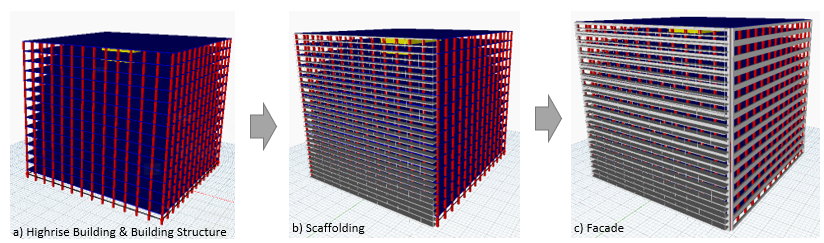
Fig 4: Integration process steps
The final model is computationally heavy, taking time to re-run our code, but is not prohibitive. The final product is a fully integrated model driven by just 3 parameters which a planner can apply to many varieties of building as demonstrated on the next page.
Download link: group_assignment3_modelling_final
Preview of the combined model: