1. Backgrund
The choices engineers make in the design of civil engineering products have far-reaching impacts on subsequent phases, including construction, operations, and maintenance. Life Cycle Analysis (LCA) provides a way to gain insight into the potential future impacts of design decisions. For example, LCA enables us to assess the environmental impacts of a particular civil system throughout its life cycle. LCA is therefore useful in helping us to consider the sustainability of a product or system design in a holistic way, so that we can better understand and manage its environmental impacts at different stages.
2. Engineering aspects
At every stage of product development, engineers must make decisions about product configuration, materials, construction, operation and maintenance. These choices are directly related to life-cycle costs and environmental impacts, and have a profound effect on overall costs and sustainability. For this assignment I would like to explore the impact of using different materials on the tunnels
2.1 Goal and scope of the assessment
The scope and boundary of this assessment is shown in the figure below.
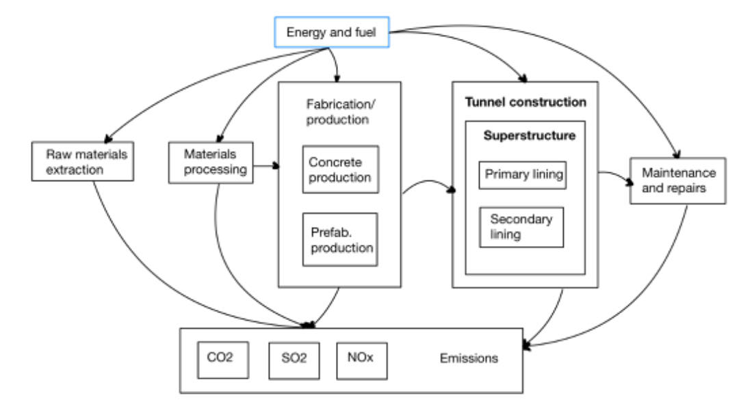
This assignment is intended for practitioners to make decisions that need to be taken when designing a tunnel lining.
Double lining is a type of tunnel structure that consists of an external primary lining (segmental or shotcrete) and an internal cast-in-place concrete (usually) secondary lining[1]. Due to the many advantages of double lining structure, its application has become more and more frequent in recent years. Therefore, I chose double lining as the research object to explore the effect of using different materials on the life cycle of tunnels. Figure 1 shows the cross-sectional structure of a double-layer tunnel lining.
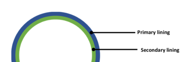
Fig.2.1.1: Tunnel double lining cross-section
The design solution I am going to analyze is shown below:
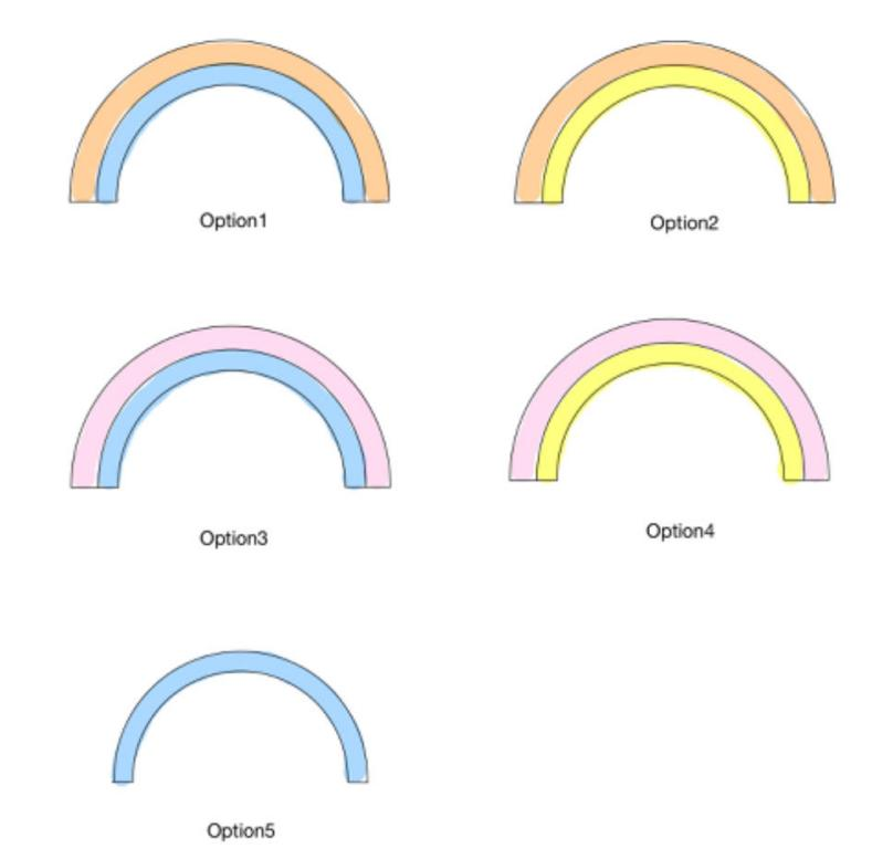
| Design option | Primary lining material | Secondary lining material |
| Option 1 | Shotcrete | Cast in place concrete |
| Option 2 | Shotcrete | Prefab concrete elements |
| Option 3 | Concrete segment | Cast in place concret |
| Option 4 | Concrete segment | Prefab concrete elements |
| Option 5 | None | Cast in place concrete |
| Element | Cross Section Area (m2) |
| Primary lining (outer perimeter = 25m,thickness = 0.20m,length=30m) | 5 |
| Secondary lining (inner perimeter = 20m,thickness = 0.55m,length=30m) | 11 |
2.2 Life Cycle Inventory of different materials, Performance, and environmental indicators
The table below lists the composition of the different materials used. For each material, I collected information about the energy consumption (MJ/t), CO2, NOx, SO2 (kg/m3) for manufacturing and processing.
| material | scope | quantities | energy(MJ/t) | CO2(kg/m) | NOX(kg/m) | SO2(kg/m3) |
| Cement | RC | 155 | 3.21 | 0.814 | 0.171 | 0.065 |
| Fly Ash | RC | 55 | 0 | 0.0025 | 0 | 0.77 |
| Coarse Aggregates | RC | 1120 | 0.0033 | 0.014 | 0.0017 | 0.0017 |
| Fine Aggregates | RC | 830 | 0.0023 | 0.0053 | 0.0085 | 0.0085 |
| Reinforcement | RC | 135 | 2430 | 225 | 0.71 | 1.85 |
| Cement | PRC | 498 | 3.10 | 0.819 | 0.177 | 0.065 |
| Coarse Aggregates | PRC | 1000 | 0.030 | 0.016 | 0.0018 | 0.0018 |
| Fine Aggregates | PRC | 545 | 0.0023 | 0.0053 | 0.009 | 0.009 |
| Reinforcement | PRC | 349 | 2430 | 225 | 0.71 | 1.85 |
| Cement | SC | 1665 | 3.21 | 0.822 | 0.177 | 0.065 |
| Fly Ash | SC | 53 | 0 | 0.0025 | 0 | 0.78 |
| Coarse Aggregates | SC | 1120 | 0.0035 | 0.016 | 0.0018 | 0.0018 |
| Fine Aggregates | SC | 823 | 0.0023 | 0.0053 | 0.009 | 0.009 |
In the table, RC = reinforced concrete, PRC = Precast reinforced concrete, SC=Shotcrete, The value of each material in the quantity column corresponds to the amount of material consumed per cubic meter of product in kg/m3.
3. Life-Cycle timeline
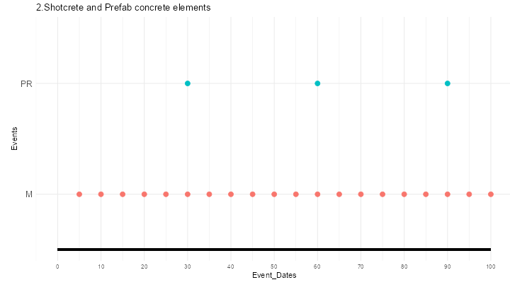
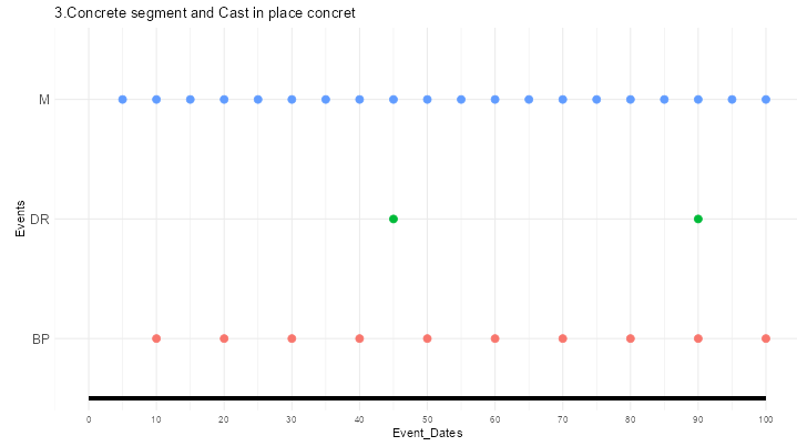
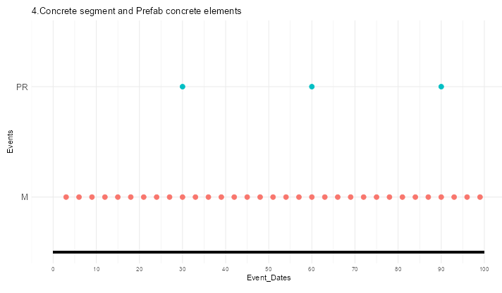
The following table shows the list of interventions for the double tunnel lining and the frequency of occurrence for each design option. Where M = maintenance , PR = partial replacement , BP = Brush Protectant, DR = deck replacement
Maintenance is the routine, periodic repair and upkeep of a structure to ensure proper functioning and prevent more serious problems from occurring. Regular inspections, cleaning, lubrication and minor repairs are performed to extend the life of the structure and reduce overall maintenance costs.
Partial Replacement is the replacement of localized components that are more severely damaged or beyond repair to ensure the integrity and safety of the structure. It is used in areas where localized damage or corrosion is more severe, while the overall structure still has good structural performance.
Brushing protectants provide additional protection against corrosion and prevent damage to the structure caused by environmental factors. Used to form a protective layer on the surface of a structure to improve corrosion resistance, especially when subjected to more severe environmental attack.
Deck Replacement is the replacement of the entire surface layer of a structure, usually due to deterioration, severe corrosion or structural damage. It is used in situations where corrosion, wear or other damage to the entire surface of the structure is more severe and cannot be addressed by localized replacement or repair.
These repairs are selected based on a combination of the overall condition of the structure, maintenance needs, economics, and impact on traffic and use. Regular inspections and assessments can help determine when which maintenance measures are needed to ensure the long-term reliability and safety of the tunnel structure.
| DesignOption | Event | Frequency | TotalLifespan |
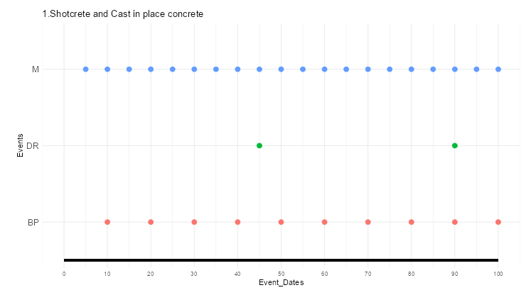
| 1.Shotcrete and Cast in place concrete | M | 5 | 100 |
| 1.Shotcrete and Cast in place concrete | BP | 10 | 100 |
| 1.Shotcrete and Cast in place concrete | DR | 45 | 100 |
| 2.Shotcrete and Prefab concrete elements | M | 5 | 100 |
| 2.Shotcrete and Prefab concrete elements | PR | 30 | 100 |
| 3.Concrete segment and Cast in place concret | M | 5 | 100 |
| 3.Concrete segment and Cast in place concret | BP | 10 | 100 |
| 3.Concrete segment and Cast in place concret | DR | 45 | 100 |
| 4.Concrete segment and Prefab concrete elements | M | 3 | 100 |
| 4.Concrete segment and Prefab concrete elements | PR | 30 | 100 |
| 5.Cast in place concrete | M | 5 | 100 |
| 5.Cast in place concrete | BP | 10 | 100 |
| 5.Cast in place concrete | DR | 45 | 100 |
With R it is possible to visualize the lifetime of the system after the intervention:
4. Life Cycle Inventory and Analysis
Once the amount of material required and the type of tunnel structure have been determined, the energy consumption can be evaluated through a life cycle inventory. We can visualize this energy consumption in R using code.
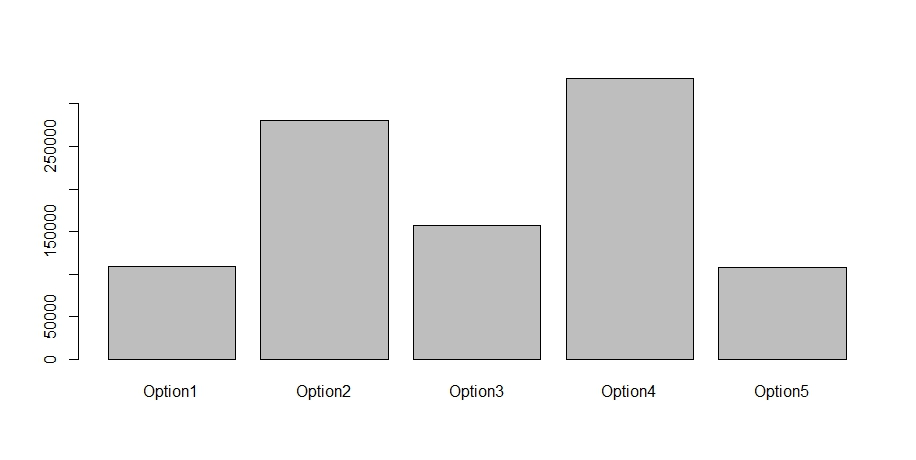
Fig.4.1: energy consumption level for different design options.
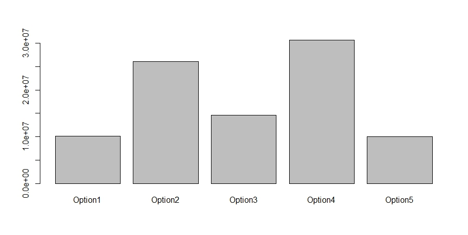
Fig.4.2: CO2 emissions for different design options
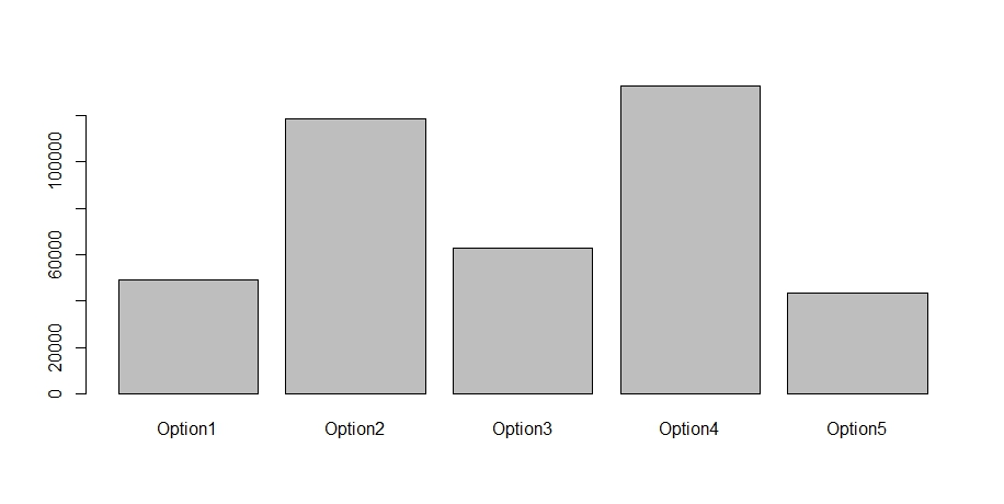
Fig.4.3: NOx emissions for different design options
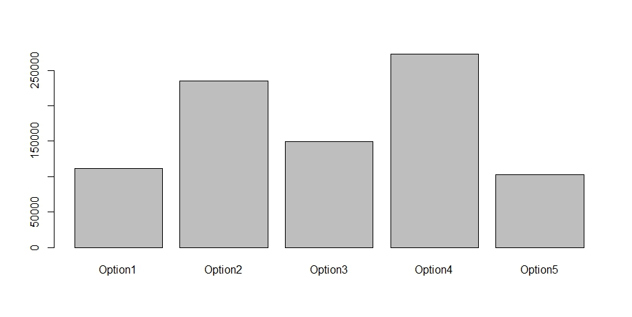
Fig.4.4: SO2 emissions for different design options
5. MCDM – Analytic hierarchy process (AHP)
Making decisions is difficult due to having multiple performance criteria, which is a multi-criteria decision making problem (MCDM). For this purpose, implementations of some MCDM methods such as AHP and TOPSIS will be investigated.
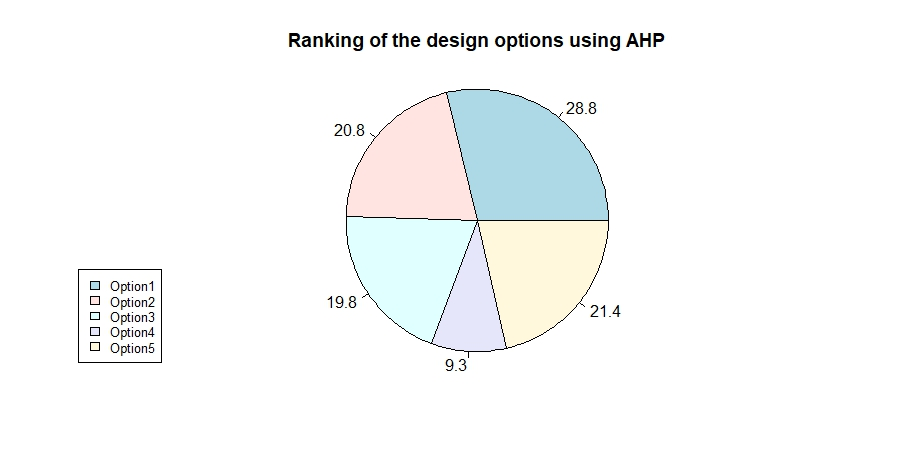
The graph above visualizes that Option 4 is actually the lowest level. Of all the indicators, Option 1 scores the highest. It also shows that Option 1 is the best decision in the given situation, with better energy consumption and pollution emissions than the other solutions. This is also in line with realistic construction decisions, as for double-lined tunnels, shotcrete is mostly used for the first layer and cast-in-place concrete for the second layer. In this design, a single layer lining structure was also added for comparison, and it can be seen that the traditional construction method also still has some advantages, but the double lining structure will be a good trend.