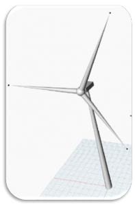
1. Introduction
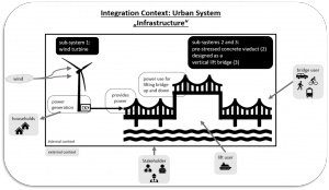
Movable bridges present the chance for an optimal usage of high-water level rivers without inflecting a change to the location’s geography, as the enable both navigation and traffic movement with minimum restrictions. Moveable bridges follow a variety of design principles such as Bascule bridge, Tilt bridge, Swing bridge and lastly Vertical lift bridges, which is considered to be the best option.
2. Ontological Model
The developed ontology targets a more specified domain within the bridge construction industry. The main purpose of developing an ontology for vertical lift bridges, is for their advantages if compared with other types of movable bridge, as they provide a wider clearance for passing ships, additionally a better utilization of the clearance elevation enabling more ships to pass through.
The developed ontology handles a variety of vertical lift bridges design variations, which corresponds to a different operational requirement, stakeholders’ choices, and the demand on functionality, according to. In addition, it handles different operation methods, ranging from simple manual control, to fully automated and responsive systems, depending on the scale of the product and its specifications, into the main categories:
- Span Drive Vertical Lift Bridge: with the operating machinery on the lift span.
- Wire Rope Span Drive.
- Rack and Pinion Span Drive
- Tower Drive Vertical Lift Bridge: with the operating machinery on the pylons.
- Wire Rope Traction Drive.
- Winch Drive.
- Connected Tower Vertical Lift Bridge.
- Pit Drive Vertical Lift Bridge: uses other operating machinery without the need for pylons.
Physical components:
Play an essential role in the parametric design, as the type of machinery is influenced by the lifted span structure, and the are broken down into the following systems.
- Support system: Sub- and Superstructure, which maintain structural integrity and stability in stationary positions:
- Abutment.
- Pedestal.
- Pier.
- Approach Span.
- Lift Span.
- Pylon.
- Collusion protection.
- Operating system (machinery): varies depending on the Bridge requirements, and the nature of the function, for example, wide lift span entails low speed, high torque, high elevation and low number of operations per year, and vise-versa, and consists mainly of the following concepts:
- Sheaves.
- Power Generators: Mechanical, Hydraulic, and electrical motors are options.
- Power Transition: Mechanical, or hydraulic.
- Breaks: Mechanical, Hydraulic, and electrical.
- Counterweights.
- Span lock.
- Cables.
- Pinion and rack.
- Balance systems: which can range from manual to electronical, to ensure no skewing would result from lift span differential movement in some design variations.
- Control systems: which can range from manual to electronical.
main material:
different scope enforces the use of a different configuration of materials, and the main structural materials used are:
- Concrete
- Steel
- Pavement and road covering
uses (functions):
depending on the scope of design the bridge can provide a passage to the following users in addition to navigation movement through the river:
- Pedestrian
- Auto (including cars, trucks, bicycles, motorcycles, etc.)
- Pipeline
- With expansion possibilities to include rail tracks.
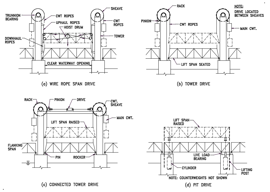
Figure 1: Vertical lift bridge components
Result Ontology:
Fig 2 shows the results modeled in Protégé, Vertical bridge domain represent the different types of vertical lift brides, with instances for Tower drive lift bridges. The uses domain shows possible traffic and navigation options. Lastly Vertical lift bridges domain presents the contributing systems in the different functions of the bridges with their possible configurations.
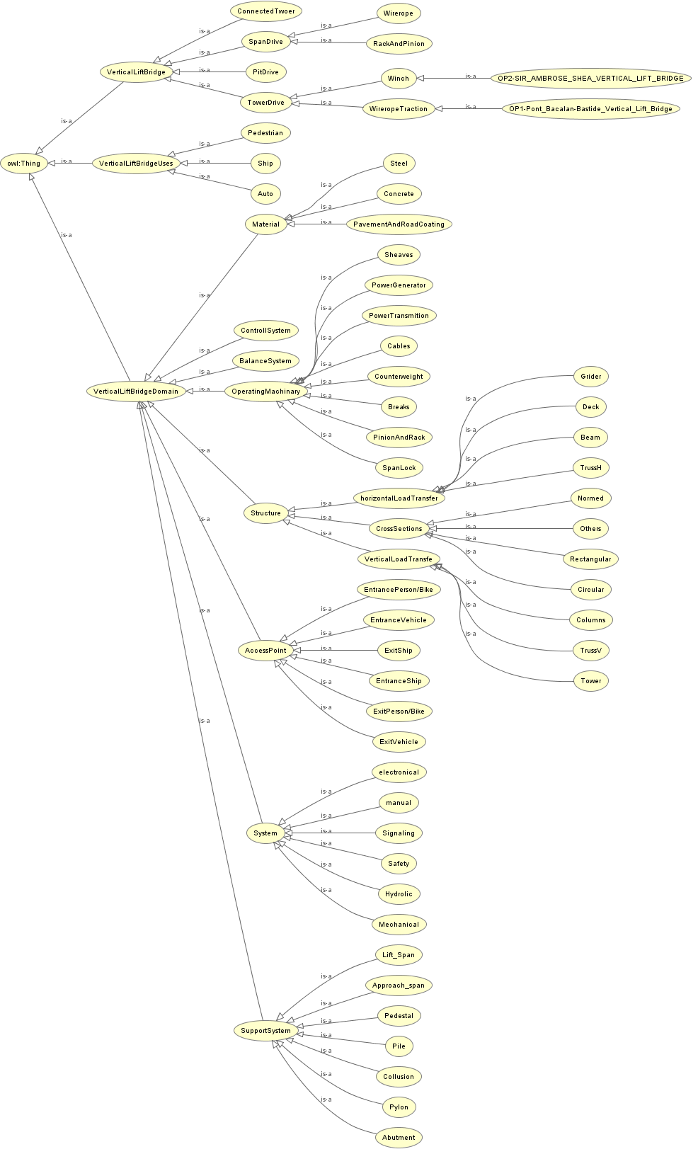
Figure 2: Visualisation of vertical lift bridge ontology
The following link provides you with the .owl file:

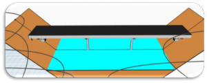
3. Parametric Model
The goal of the parametric model covers one variety of the vertical lift bridges ontology, namely the Tower drive lift bridge, as this option enables the maximum use of a river’s width, additionally fits a minimal power consumption for a narrow river where it utilizes the use of counterweights. When carried out carried out carefully the model help to find an engineered product that fulfills high performance criteria of:
- optimal renewable energy use
- Amounts of materials
Parameters chosen for the model follows AACHTOO recommendations for bridges:
- lane width
- Sidewalk width
- Middle separator width
- ift span length
- Tower heights
- Lift height
- And other structural parameters related to the structural aspect of the bridge
The following figures show the parametric model:
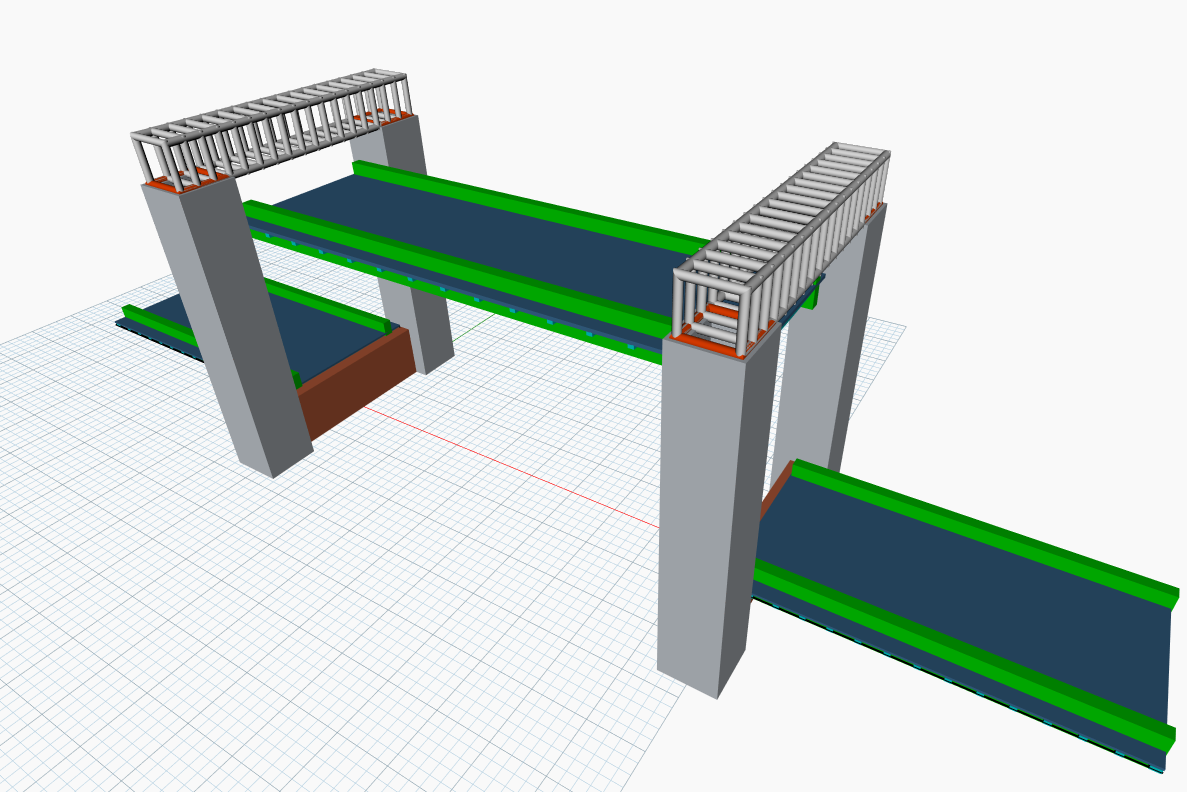
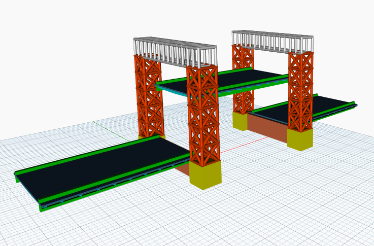
A visualized dynamic version of the lift span can be seen in the Integrated model visualization.
The following link provides you with the .dyn file:

go to