Table of contents:
- INTRODUCTION :
II. DESIGN CHALLENGE AND HIGH PERFORMANCE CRITERIA :
III. THE LOGIC OF THE PARAMETRIC MODEL :
IV. Design Space evaluation and ideal designs representation :
1- Design space Evaluation :
2- Ideal Design Alternatives Representation :
List of Figures:
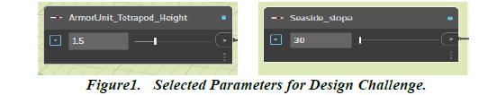
Figure1. Selected Parameters for Design Challenge. .
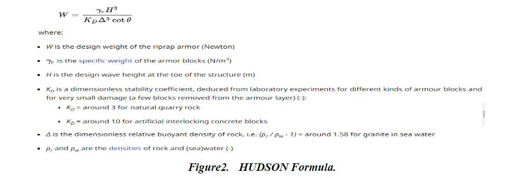
Figure2. HUDSON Formula.
Figure3. Parametric Model Implementation in Dynamo BIM.
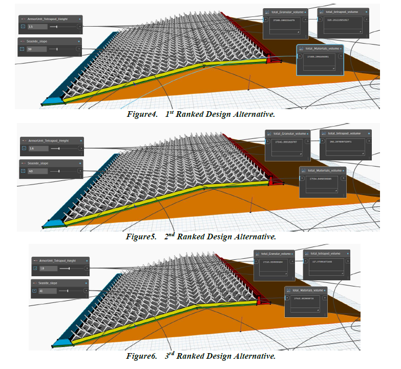
Figure4. 1st Ranked Design Alternative.
Figure5. 2nd Ranked Design Alternative.
Figure6. 3rd Ranked Design Alternative.
I .INTRODUCTION :
Recognizing their huge benefits and facilitations, reflected by their ability to rapidly generate multiple alternative designs, accompanied by the possibility to visualize and explore their corresponding geometrical configurations, the development and penetration of the parametric modeling practices into civil engineering field is actually surging and expanding. Therefore, by Building on the ontological model implemented previously for the rubble mound breakwater system, this project aims at creating its respective parametric model through Dynamo BIM software. Firstly, we will expose the design challenge and the criteria adopted to assess the performance of the controlled parametric design. We will secondly illustrate the logic underlying the developed parametric model. Finally, we will carry out an evaluation and discussion of the design space, given its extremes and constraints, and represent the ideal design options that satisfy the performance criteria.
II .DESIGN CHALLENGE AND HIGH PERFORMANCE CRITERIA :
The principal function of the breakwater is to minimize the agitation inside a specific basin and protect it from aggressive incident waves, in order to meet the vessels requirements related to berthing and mooring operations, which justifies the incorporation of multiple layers, ranging from the Core component until the armor system, and their associated excessive set of parameters that shape their physical embodiment, as showcased by the parametric model. However, to narrow the broad range of parameters and the scale of experimentation to be conducted, it was elected to restrict the controlling parameters to the individual cone height of the Tetrapod armor unit and the slope accorded to the side confronting the sea. Figure1 highlights their corresponding number sliders defined in Dynamo BIM.
Acknowledging the large amounts of materials consumed by the construction of these structures, the high performance criteria adopted in our case consist on the following :
• Optimizing the overall volume of materials integrated respectively in the armor, filter, underlayer and the Core layers of the breakwater.
• Mitigating the overtopping effect, manifested by the passing of water over the structure.
• Ensuring the basin’s protection and maintaining the structure’s stability and the continuity of the service. This criteria will be evaluated based HUDSON Formula illustrated in the figure2 below, which serve to determine the armor unit weight needed to support and dissipate the loading energy applied by wave propagation :
III. THE LOGIC OF THE PARAMETRIC MODEL :
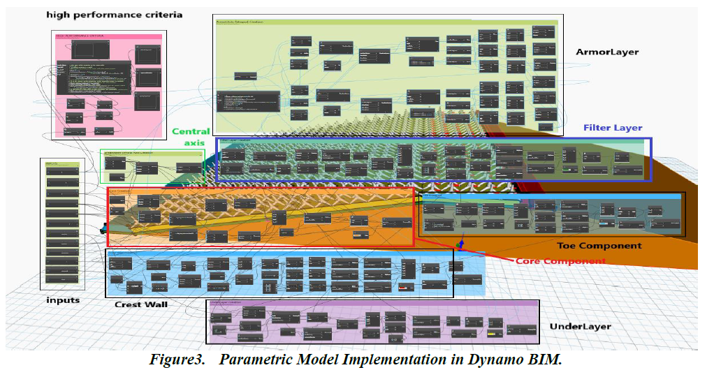
In the objective of establishing a complete parametric model that represents the rubble mound breakwater, an effective workflow process was pursued as schematized in Figure3. In fact, the designing priority was attributed to the Core component, as it influences the other subsystems configurations, with its geometry set up to be manipulated by the height, width and the sides slopes. The implementation of the Crest Wall was proceeded at the nest step, since the latter lies directly on the Core, where its height and the width of its related deck platform were identified as the inputs that adjust its design. the subsequent part was the filter Layer, whose thickness was defined as an input parameter, and which covers the entire Core system by extending beyond its base, until it intersects with the Crest Wall. Next, the Toe component was created and placed above the filter Layer besides the Core to confront the sea, with its height and width identified as parameters that refine its configuration. While the Underlayer and the Armor Layer are localized between the Toe and the Crest Wall, they were subsequently the last parts to be modelized, accompanied respectively by the thickness and the armor unit height to allow the refinement of their geometrical embodiment. Finally, Code script was integrated in the design space to check the conformity and the performance of the design alternatives with respect to the precited high performance criteria, as displayed in the figure above.
IV. Design Space evaluation and ideal designs representation :
1- Design space Evaluation :
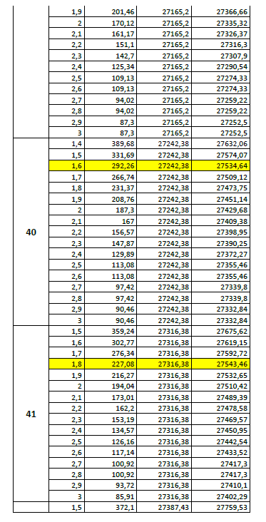
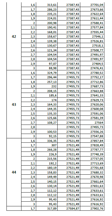
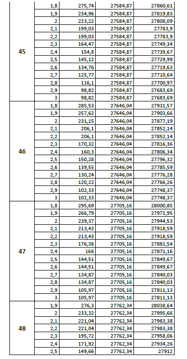
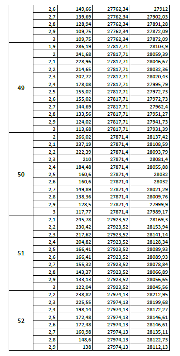
Exploiting the flexibility offered by the parametric model to easily produce design alternatives, based mainly on the interactions occurring between the different nodes and code scripts inserted in Dynamo BIM, we will elaborate an evaluation experiment of the design space, that seek to identify the optimal design configurations that satisfy the precited performance requirements, by concentrating the parameters refinement process on the ones mentioned above, while keeping others fixed. On the other hand, this experiment will contribute to resolve the conflicting effect of the two parameters. In effect, while increasing the seaside slope yields an augmentation in the amount of materials incorporated in the core, underlayer and filter layers, it has an opposite impact on the total volume of the concrete incorporated in the armor layer, which is caused to reduce. The latter act can be explained by the fact that two parameters are bound by the Hudson Formula, where rising the seaside slope leads to the increase of the armor unit, which consequently induce a drop in the number of units distributed over the underlayer. Hence, finding the convenient value pairs remains the essential challenge of this project.
In this context, the iterative process that underpins the experiment approach consists on incrementing the seaside slope by the related step specified in the model, to define the minimal height corresponding to each incrementation, that meet the stability requirement using the Hudson Formula. Starting from the minimum obtained, we proceed at incrementing the height to evaluate the potential optimization that can be derived from the respective design options. The overtopping criteria will be qualitatively assessed based on the geometrical embodiment of the breakwater, taking into account that steep slopes and widely dispersed armor units (bad interlocking) produce higher wave reflection and intensify overtopping. By combining the criteria considerations illustrated above, we will represent in the next section the three ideal design alternatives detected through the experiment.
2- Ideal Design Alternatives Representation :
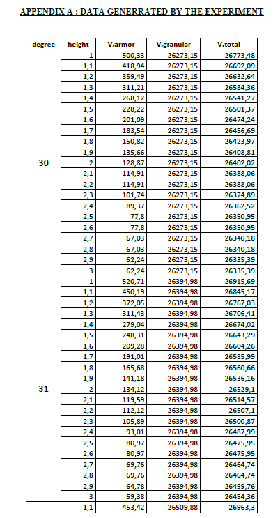
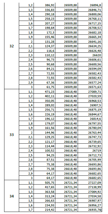
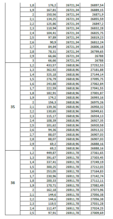
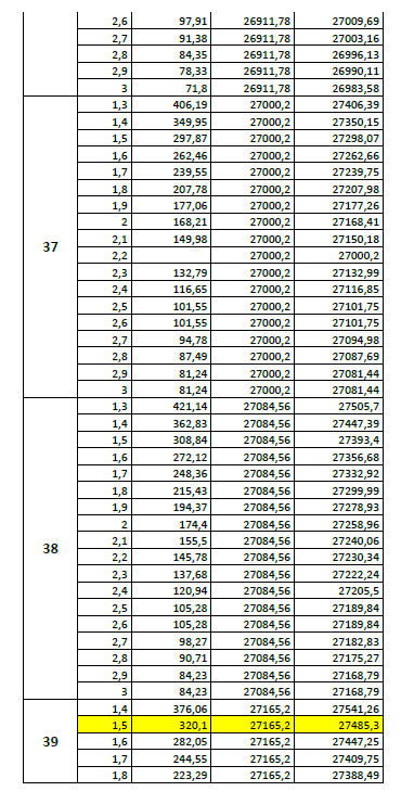
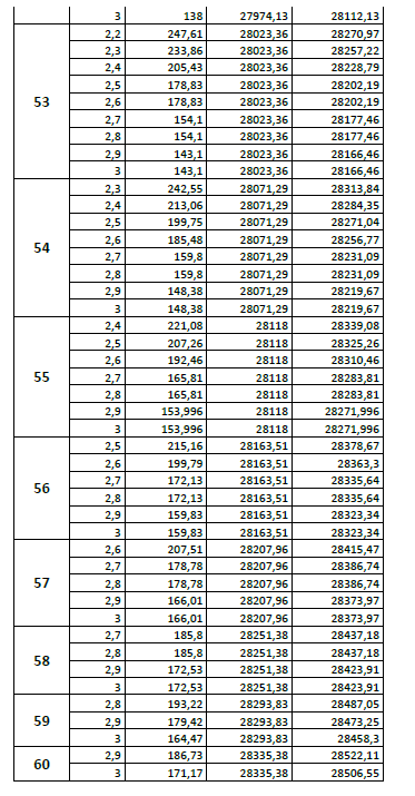
Referring to the data generated by the variation of the predefined two parameters within the acceptable range affected to them in the model, the figures below represent the ideal three design alternatives that meet the high performance criteria. The selection procedure is explained by the following reasoning :
As the excessive declining of the seaside slope will exacerbate the overtopping behavior, whereas its large increase will reduce the number of armor units placed above the underlayer, to a point that will not be sufficient to limit the overtopping effect, from the other hand, considering the significant amount by which the overall granular volume of the layers is increased whenever the seaside slope is incremented by one degree, which its average is estimated at 68,73 m3, it was decided to keep the granular volume of the selected alternatives around the average corresponding to all generated options, which is equal to 27.304,25 m3.
Since the overtopping criteria requires a reasonable dense number of armor units to ameliorate the interlocking aspect, we looked at maximizing the density of the armor units deployed, while keeping the height above the minimum specified by the Hudson Formula and the global volume of materials constant among the design alternatives.
Here you can download the Full Parametric Model: Breakwater