Introduction:
The bridge represents a critical connection Structure and has a major Influence on
social and economic events of any country, city, or community. It is essential to the
transportation of Goods and movement of People across all sorts of obstacles. Steel
Bridges have played a large part in fulfilling these Roles since the Beginning of the 19th
Century.
Steel itself is a ductile Material suitable for construction, it has a Yield stress of about
240 MPa and tensile strength about 360 MPa for normal Strength structural steel,
Structures also made of Steel can be constructed in less Time and offers a large Variety
of design options and supports Flexibility during both Manufacturing and Construction.
Designing a Steel bridge is mainly influenced by the Dimensions required for the Bridge
as well as the main Use for it, which determines the Different Loads and Strains it will
be subjected to, which in turn reflects on its Dimensions and Structural System.
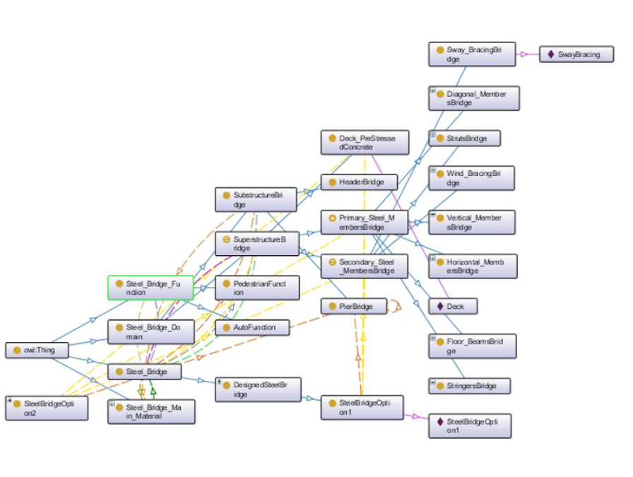
Ontology Model :
• What is the purpose? – This ontology is developed to represent the main Structure
and Components of the Steel Bridge and to provide a clear Representation of both its
Sub-Structure and Super-Structure.
• What is the scope? – This ontology includes concepts such as the Materials used in
Bridge Construction, main Structural Components as well as the possible bridge uses
and their relations.
• Who are the intended end-users? – The intended end-users are the Civil Engineers
and construction technicians who are responsible for constructing and maintaining the
Bridge.
• What is the intended use? – The ontology is intended to be used as a Framework to
model the Bridge and understand its main Components and the materials used in its
Construction as well as aid in its modelling and any necessary repair Procedure.
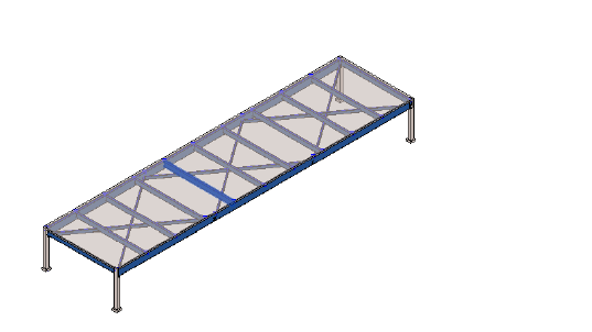
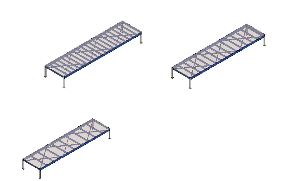
Parametric Model:
The Bridge Consists of Concrete Slab (thickness=25cm) whose load is transmitted to
cross Steel Girders which are in turn placed atop the Main Steel Girders and Finally
these are placed on Concrete Abutments.
There is also lateral and upper Bracing for Between the Main Girders.
The designed Parametric Model offers us a large degree in determining the Dimensions
and no. of Cross Girders that are present in the Bridge according to the following
specifications:
| Input Parameter | Max. Value | Min. Value | Step |
| Bridge Length | 50 | 10 | 1 |
| Bridge Width | 12 | 3 | 1 |
| Spacing between Cross Girders | 1 | 15 | 0.5 |
This in Turn allows us to better examine the different Stresses resulting on the main
Structural Components when varying the different Input Parameters which allows the
Designer to make informed Decisions.
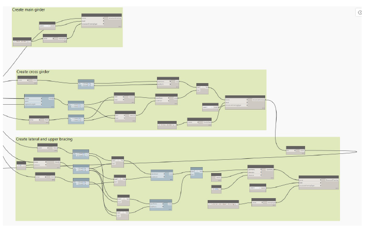
This represents the part of the Dynamo that is responsible for creating the main
Structural elements of the Bridge: Main Girders – Cross Girders – Lateral and Upper
Bracing
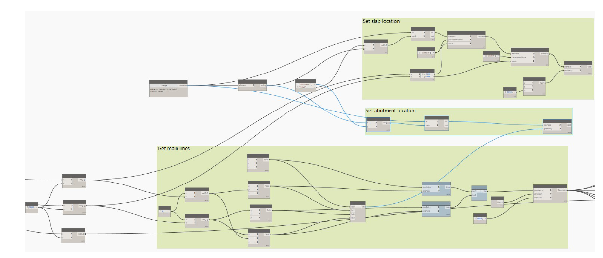
This part defines the main Lines and Coordinates of the Bridge as well as the position of
the Slab and Abutment.
And finally we have this Part which calculates the loads on the Bridge using
approximate Equations and also allows us to change the Input Parameters using Slider
Nodes and observe the effect on Stresses on Structural Members.
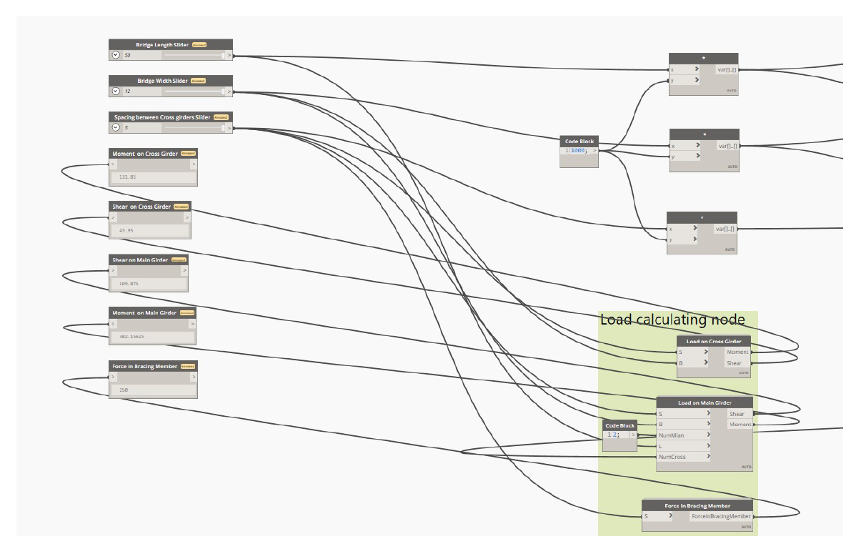
We notice from the Model that the most important Parameter in our structural model is
probably the Spacing between the Cross Girders as it has a noticeable effect on the
Straining actions on all the Structural Elements: Main Girders – Cross Girders – Lateral
and Upper Bracing.
The High Performance Criteria are:
1- The Deck Area of the Bridge which should be maximized but within the allocated
Project Budget.
2- The No. and Dimensions of the Bridge’s Structural Elements which should be
minimized to make the Bridge more economic.
Ideally the Designer would specify the Length and required Width of the Bridge and then
vary the Spacing between the Cross Girders.
But another option would also be to specify the Spacing First and then adjust the
Dimensions of the Bridge itself (Length and Width).
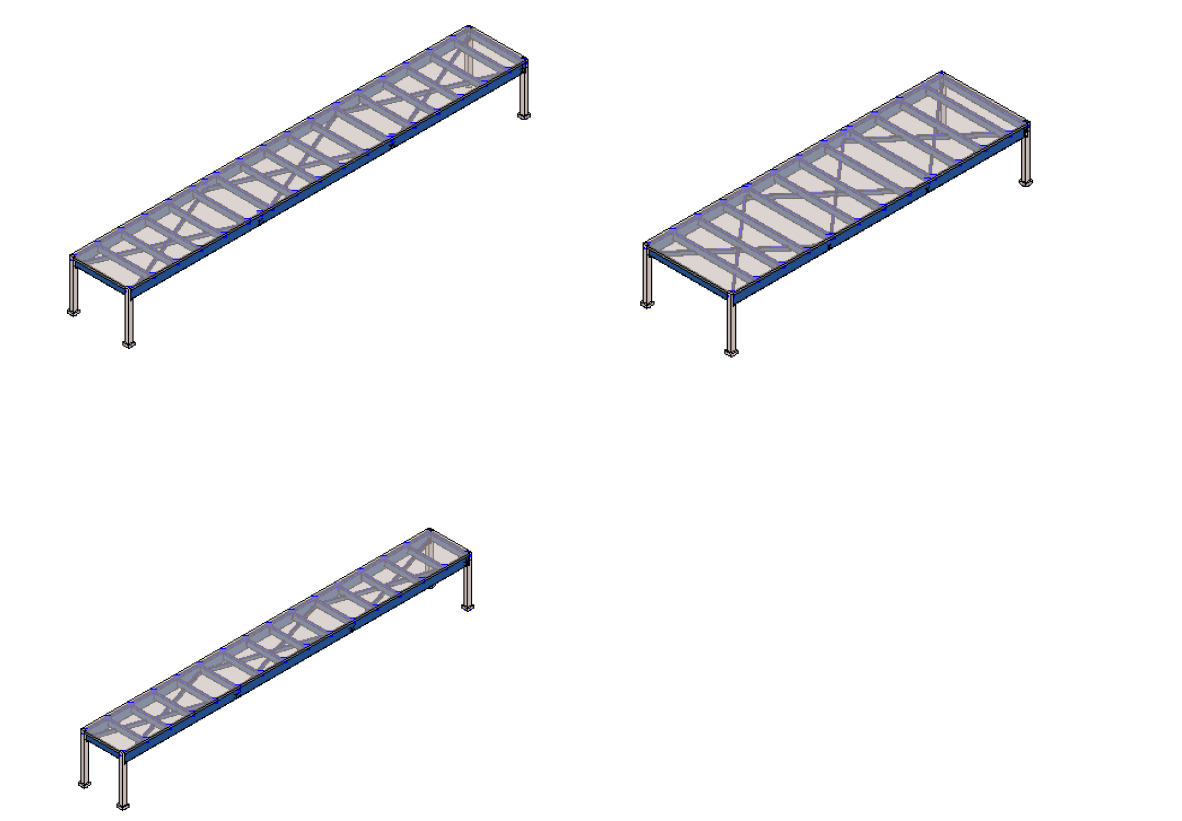
The Choice between any of these two methods would depend on the Constraints
that the Project is subject to.
Here you can download the OWL File for the Ontology:steel-project-ontology
Here you can download the Parametric Model (please make sure to open the Revit file first and then open Dynamo File from within Revit in Manage Tab so that the visualization works):steel-bridge-script