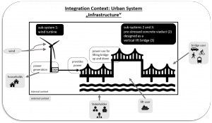
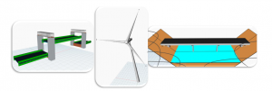
The 3D models below show the two options of the final integrated model of the three systems, a site model is used to generate the configuration of the: Viaduct approach spans, lift bridge and the wind turbines.
The parameters of the site influence the generated outcome through the following input parameters and are also shown in figure 1:
- Slope height: geography of the site
- Slope angel: geography of the site
- River width: geography of the site
- Lift span length: set by navigation requirements
- Viaduct span length: Structural considerations
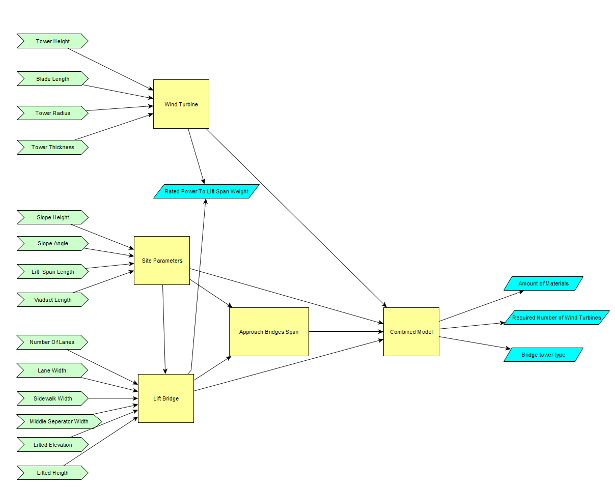
Design Process:
- The site parameters are streamed using Speckle nodes in the beginning to the parametric model of the Lift Span, where the width of the approach span is influenced by requirements of the lift span, such as the number of lanes and their width corresponding to traffic requirements. Additionally, the lifted height and the towers height is a separate parameter, which follows the navigation requirements. The structure of the towers is chosen automatically based on the weight of the lift span, which again is influenced by the in-streamed site parameters.
- The site parameters and the bridge width are imported to the Approach span parametric model; this model contains no manual input parameters. Where it generates automatically to symmetric approach bridges to both ends of the lift span.
- The Wind turbine has a set of independent input parameters as their relation to the site is irrelevant, if they are constructed onshore. But the important output of this model is the generated, and the geometry of the wind turbines.
- The returned stream of information, updates the final configuration of set to the site, where it automatically generated the wanted number of wind turbines, according to power needed to lift the movable span.
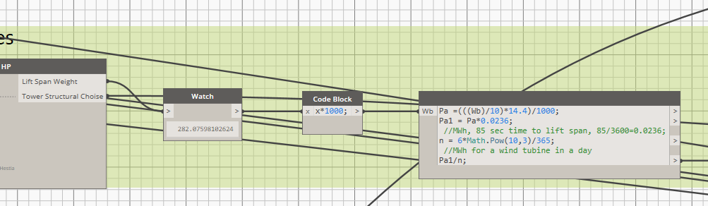
For the calculation of the number of wind turbines [1] is used as an approximation for the power needed, the reference uses water counterweights. The calculation is shown in figure 2:
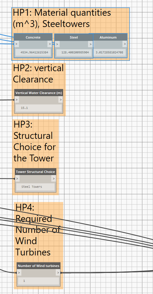
The HPC calculations of the two options are shown in figures 3 and 4.
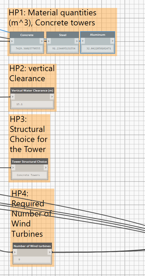
Option 1 Concrete
Option 2 Steel
The following link provides you with the integrated .dyn file:

You will also need the adapted individual models for running the integrated model:
Group 8 – vertical-lift-bridge
go to
References:
[1] Water Operated Vertical Bridge Lifting: https://www.ijser.org/researchpaper/Water-Operated-Vertical-Bridge-Lifting.pdf