➢ SYSTEM:
Rigid pavement is a type of concrete pavement that is composed of a thick concrete slab that is supported by a subgrade and foundation system. It is known for its high strength and durability, making it suitable for high-traffic areas such as airports and industrial parks. Unlike flexible pavements, which rely on asphalt to provide a flexible surface, rigid pavements are rigid and do not deform under heavy loads. This results in a smoother and more stable riding surface that is less prone to cracking and other forms of damage.
➢ SUB-SYSTEM:
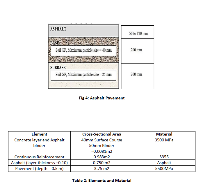
For this system, Slab, base and sub-base are considered as a sub-system of the entire Road constructed. Slab consists Concrete, steel reinforcement, asphalt and its primary function is to provide a smooth and durable riding surface for vehicles. The base is the layer below the slab and is made of crushed stone, gravel, or other aggregate materials. Its purpose is to provide support for the slab and distribute the weight of vehicles evenly. The subgrade is the layer of soil or material that is beneath the base and provides the foundation for the entire pavement system. Its function is to support the weight of the pavement and prevent settling and erosion.
From them I am choosing Slab as the sub-system of this project.
➢ GOAL AND SCOPE ASSESSMENT:
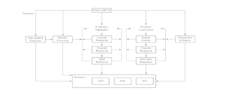
Goal of this project is to do the carbon footprint analysis and find out the amount of energy consumed, CO2, NOx and SO2 emission from each material of the subsystem and from the construction procedure of the System.
Figure below shows the scope and boundary condition of the system.
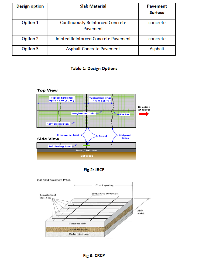
 ➢ DESIGN OPTIONS:
For the chosen system I have applied the following changes with the different material and different variables in the Slab of the pavement.
➢ LIFE CYCLE INVENTORY:
Following table illustrates the different material used in the construction procedure and their data about energy consumption, emission of CO2, NOx and SO2.
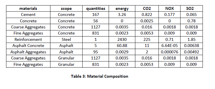
In the table the quantities of Concrete, steel and Asphalt is represented for 1 m2 of concrete, 1 kg of steel and for asphalt, the values indicated represent percentages of various materials used in 1 cubic meter of asphalt, such as 5% is asphalt cement and 95% aggregates/Concrete.
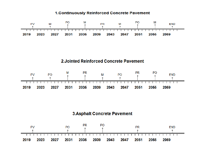
➢ LIFE-CYCLE TIMELINE:
The timeline for three different types of concrete slabs (asphaltic concrete, continuously reinforced concrete, and joined concrete) used in the construction of road pavement is shown in the plots below. The typical expectation for the pavement lifetime is a life cycle of 40 years.
The notions for the plots are PO, M, PR and END which represents Pavement Overlay, Maintenance, Pavement Replacement and End of Lifecycle respectively.
Option 1: PO = 10, M = 5, PR = 20, END = 40
Option 2: PO = 5, M = 10, PR = 10, END = 40
Option 3: PO = 10, M = 10, PR = 15, END = 40
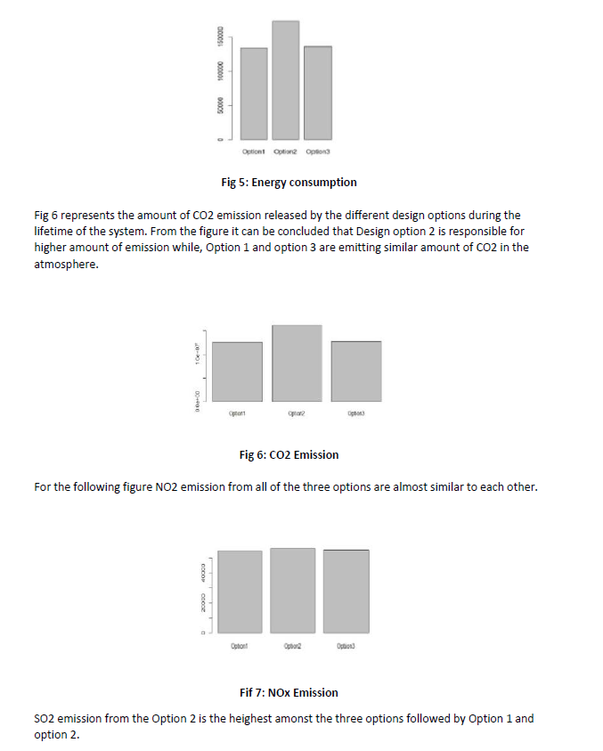
➢ LIFE-CYCLE INVENTORY ANALYSIS:
After the life cycle inventory analysis of these three options, following plots were generated.
From Fig 5, which represents energy consumptions of different options, we can say that Option 2 which is jointed reinforced concrete Requires the maximum energy of 20000 MJ/t. whereas option 1 and option 2 with continuous reinforced pavement and asphalt concrete pavement need equal amount of energy.
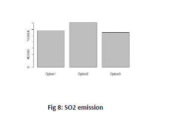
➢ CONCLUSION:
According to the analysis of this project it can be concluded that the Option 1 (Continuously Reinforced Concrete Pavement) and the Option 3 (Asphalt Concrete Pavement) are the most suitable for the final design option as it contributes less amount towards the emissions of the CO2, NOx and SO2. It also consume the lower amount of energy compared to option 2 (Jointed Reinforced Concrete Pavement), which requires the highest amount of energy during the lifetime of the pavement system.