Cable-stayed structures are the youngest, fastest-developing, and most promising bridge systems. [1]
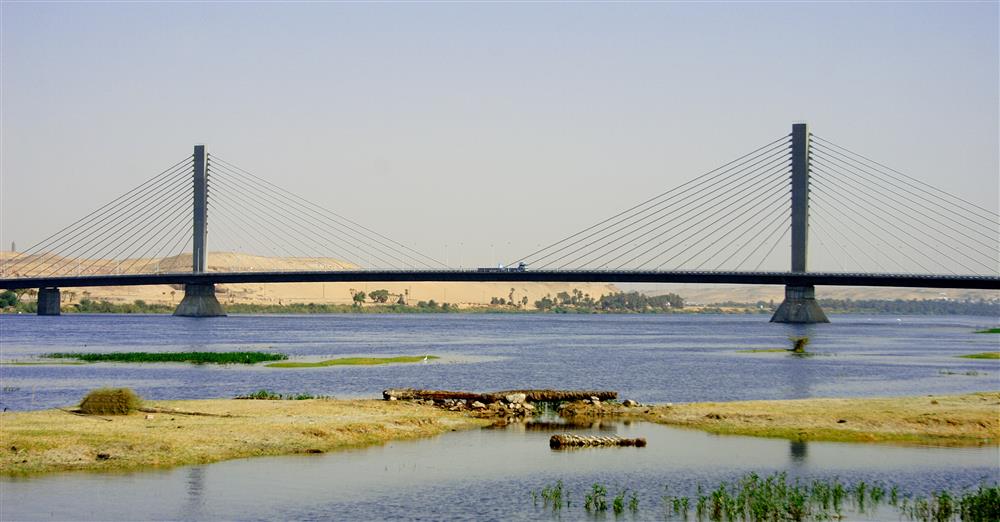
A cable-stayed bridge is characterized by the efficency in cost, materials and construction time. It ranges from 100-meter spans to over 1000-meter spans. A cable-stayed bridge is similar to a suspension bridge which has pylons and a deck-girder supported by cables. However, the difference to suspension bridges is that the diagonal cables directly transfer the vertical loads from the deck to the pylons. Thus, the deck-girder acts like a beam. Another interesting fact is that the cable-stayed bridge is a prestressed system. Thus, under dead loads the deck-girder shows little deformation due to the pretension of the cables and the extended installation of the deck-girder and pylons.
As every other system, a cable-stayed bridge must cope with all environmental conditions on the site. The durability is dependent not only on the protection and waterproofing details but also on the inspection and maintenance strategy.
Subsystem: Pylon
In the previous assignment a life cycle analysis has been conducted for the pylon (also known as mast). The pylon is an important structural element since it needs to carry pressure forces resulting from the forces of the cables which are in tension. In the bridge design, three material options are common: steel (design option 1), reinforced concrete (design option 2) and steel-composite (design option 3).
Each material has its own failure rates and therefore, the maintenance plan can be defined differently for each design option. Examplarely, the maintenance plan for design option 2 is shown in Figure 1 below. The abbrevations are defined as follows: visual inspections (SI), major inspections (MI), surface repair (SR) and structural repair (MR).
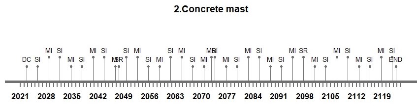
Figure 1 – Maintenance plan for design option 2
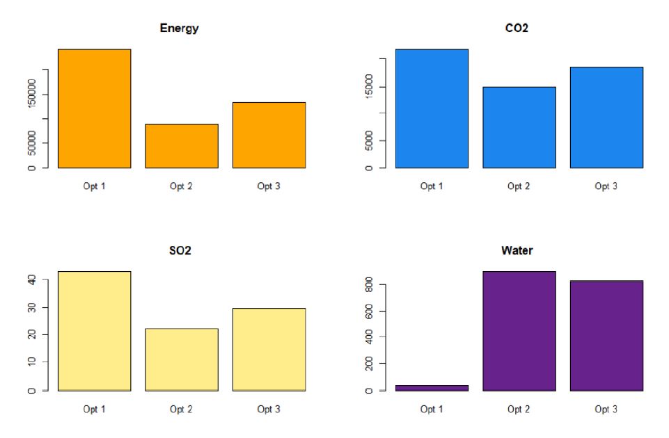
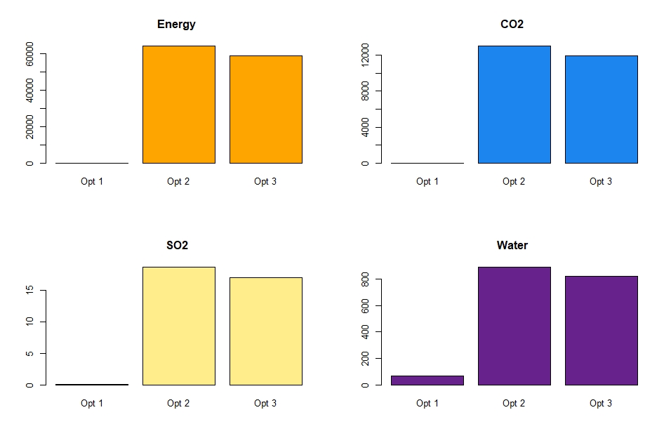
Five different indicators were taken into account in the life cycle analysis: energy consumption, CO2, SO2, water consumption and cost. Figure 2 shows that the design option 2 gives the lowest values for energy consumption, CO2 emission and SO2 pollution. Only for the water consumption, design option 1 seems to be the best option.
Figure 2 – LCA results for energy consumption, CO2 emission, SO2 pollution and water consumption for each design option
As a multi-decision method, AHP is chosen to be conducted. As Figure 3 shows that the winner is design option 2 which is comprehensible since the results from the LCA above already showed that design option 2 has lower impact on the environment. Nevertheless, it needs to be mentioned that eventhough the CO2 emission of steel during the production phase is higher, steel can be recycled and reused which is not taken into account in this analysis.
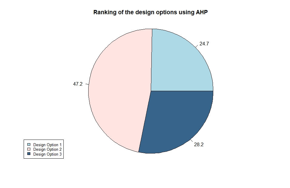 Figure 3 – AHP results
For the establishment of the integrated system, the reinforced concrete cross section is chosen for the pylon.
[1] Cable-stayed bridge, website: https://www.structuremag.org/?p=16503
[2] Mike Schlaich et al., 2019, Structural Engineering Documents – Extradosed Bridges.