Ontology for structurally designing steel framed factory.
For a well-developed ontology we need first to define the scope, the purpose, the function, and the components of the system, so we will first define these aspects.[3]
Purpose of ontology: To structurally design a well-structured steel framed factory, with the implementation of some other systems to form an efficient, safe, and adaptable to market change, environment friendly environment. This ontology could be used to help design different types of steel framed factories, dealing with different data.
Scope of Ontology: This ontology includes concepts such as factory physical components, possible materials, factory uses, equipment, systems, and their relations.
Who are the intended end-users? – The intended end-users are the designers and engineers involved in the design process.
What is the intended use? The ontology is conceived as a knowledge representation framework intended to underpin the development of parametric models. Its primary focus is directed towards facilitating structural analysis, particularly within the context of generating and utilizing parametric models for this purpose with the integration with different systems.
Functions
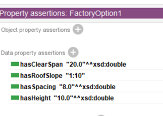
Returning to my specific system, it’s a steel structured production factory of these properties:
- Length = 80 m
- Width = 45 m
- height = 10 m
- Spacings = 8 m
- Roof slope = 1:10
- Worker’s capacity = 1000 workers
- Production rate = 5 ton/day
The model is mainly divided into:
- Factory
- Factory main materials needed to be considered while designing a well-structured steel framed factory, this classification primarily determines the primary material of the factory, typically influenced by the materials utilized in both the superstructure and substructure. For the material used, I indicated only the material used for substructure and superstructure, even though there are other components with more materials.[4] We use hot-rolled structural steel sections, which is a high-strength carbon steel alloy. Structural steel offers a balance of strength, ductility, and durability. It is produced through controlled processes, compared to old cast iron which is made by melting iron and pouring it into molds. It was appreciated for its strength in compression but had limited ductility. [5]
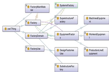
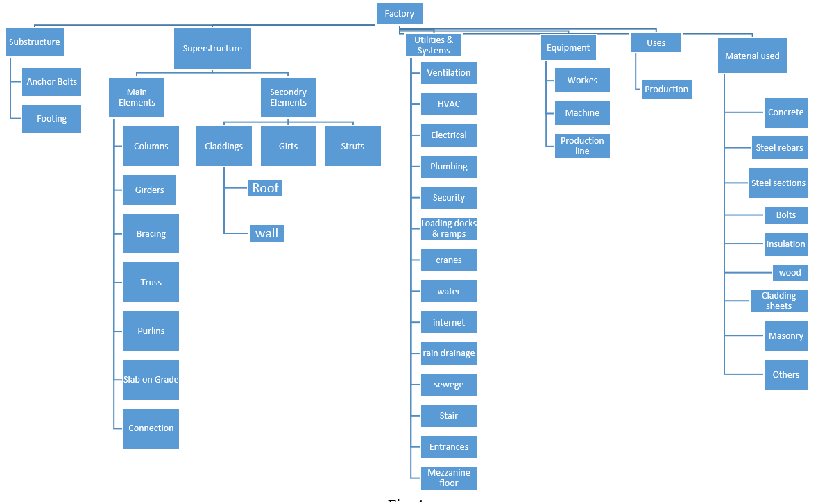
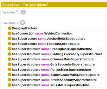
- Factory domain which is divided into physical components (substructure, superstructure, utilities and systems and equipment). The domain signifies the primary emphasis of factory structural engineering, wherein the factory configuration is divided into 4 primary sub-divisions (as shown in fig.1):
- Substructure: The substructure pertains to the segment of the factory in direct interaction with the soil and typically functions as a foundation for the superstructure
- Superstructure: The superstructure of a factory refers to the part of the structure that is above the foundation or substructure. It includes all the components and elements that contribute to the building’s overall form and function.
- Equipment: (workers, machines, and production lines) The importance of machines and workers in a factory is significant, as they play crucial roles in the production and operation of the facility. In the context of structural design, the presence of heavy machinery and equipment in a factory imposes additional considerations. The structural design must account for the dynamic loads generated by machines, such as vibrations and impact forces.
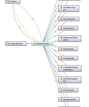
- Systems: Adding systems and utilities, although some of them will have no effect on my designing ontology itself, I believe it is necessary to include them simply to demonstrate that there is no factory without these systems. implementing systems like HVAC and electrical systems in a factory is imperative for the well-being of workers, the efficiency of manufacturing processes, and compliance with regulatory standards. These systems contribute to a safe, comfortable, and productive working environment while supporting the reliability and longevity of equipment. (As shown in Fig.2) [9] [10]
In the context of structural design, for example, if we consider HVAC system alone and see how it is affected by the designing process, the heating, ventilation, and air conditioning (HVAC) requirements are influenced by the size, shape, and insulation of the factory structure. Large open spaces, ceiling height, and insulation choices can all have an impact on thermal performance, requiring changes to HVAC system specifications. In addition to the ducts weight which will be supported on the frame, this added load must be considered in the design process.
- The use: which is designing factories for goods production.
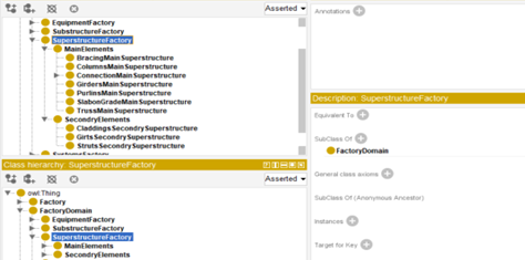
Now, we will take “SuperstructureFactory” as an example to describe.
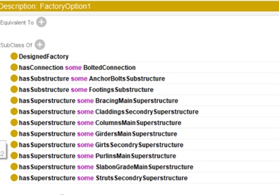
- “SuperstructureFactory” is a subclass of FactoryDomain
- “SuperstructureFactory” has 2 subclasses: Main elements, Secondary elements.
- I have classified the superstructure into two subclasses based on essential and non-essential elements. The former comprises indispensable components crucial for the structural integrity and safety of the frame, such as beams, columns, and bracing. In contrast, the latter encompasses secondary elements that contribute to the overall completeness of the frame but do not compromise the structural safety if omitted, such as claddings
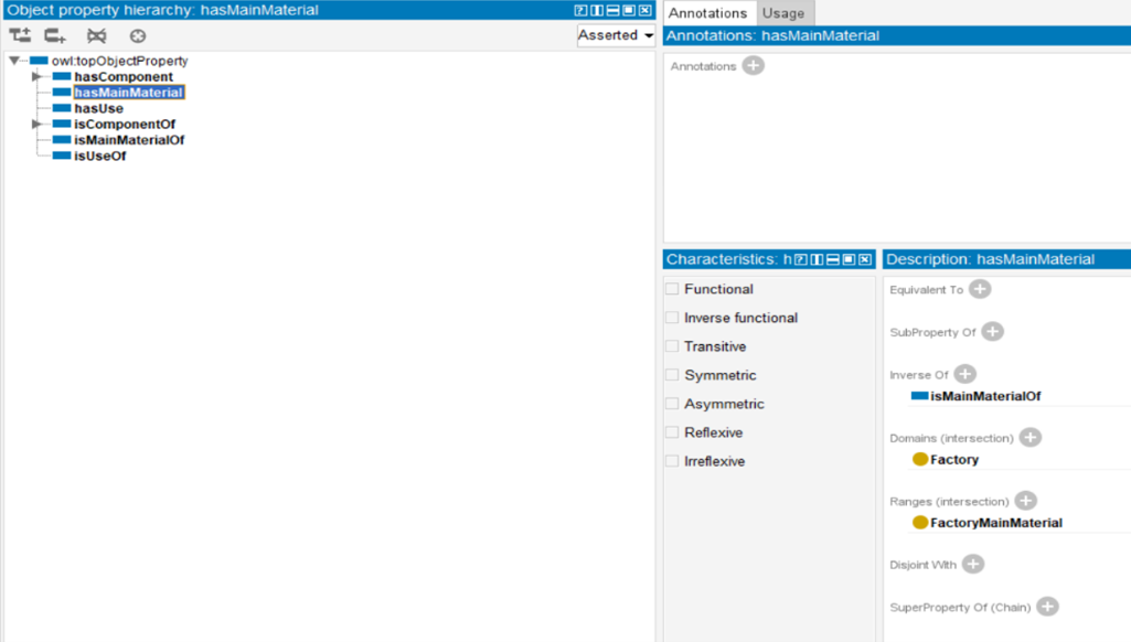
Now, let’s take an example from object properties “has main material”.
- To know the domain of this property, we should ask: what has main material? It’s the Factory.
- Similarly to know the range, we should ask: what class this property should be an instance of? Its
- hasMainMaterial is inverse to isMainMaterial of, where the latter property has the opposite domain and range. The importance of the inverse property is that it allows you to navigate the ontology in both directions. For instance, if the designers want to query for all structural elements that have a specific main material, the inverse property simplifies the query.
And here is a graph summarizing the system’s components and its types:
Presented herein is a tabular delineation illustrating the allocation of materials across various structural elements.
| Element | Material |
| Footings | Concrete + steel rebars |
| Columns | Steel section – IPE |
| Girders | Steel section – IPE |
| Bracing | Steel section – Double angle |
| Truss | Steel section – Single angle |
| Purlins | Steel section – [ section |
| Girts | Steel section – Box section |
| Struts | Steel section – Box section |
| Slab on Grade | Concrete + steel rebars |
| Claddings | Sandwich panel (Cladding sheet + insulation) |
| Connection | Bolts/ weld |
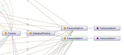
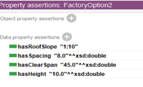
Within the Protege interface, two distinct design alternatives are evident, differing solely in the primary beam selection-either a primary girder or a truss. This dichotomy arises due to the factory’s width of 45 meters, with the maximum feasible clear span for a primary girder capped at 20 meters and the typical truss accommodating a clear span of approximately 50 meters. [6][7]. Consequently, the design options encompass achieving a clear span through the utilization of a truss girder or adopting a multi-span configuration utilizing the primary girder. Another thing, the truss girder will be all welded because in my opinion, welding creates a continuous connection between truss components, enhancing the overall structural integrity. This continuous connection helps distribute loads more uniformly throughout the truss. While for the beam type girder we will use bolted connection because as the beams are already supplied in extended lengths, it will be good idea to use bolted connection, as bolted connections allow for easier transportation of individual components, particularly when dealing with large or complex structures. This can simplify the logistics of transporting and installing structural elements. [8]
In the properties of each option, I indicated the maximum clear span that could be achieved in each option.
Engineering Examples:
- Collaboration between different parties
Scenario: A construction project involves collaboration between architects, structural engineers, and contractors.
Use case: My ontology can define concepts like design parameters, material specifications, and construction methods. This helps in creating a common understanding among team members from different disciplines and ensures consistent communication throughout the project.
- Expanding the clear span to introduce new production line.
Scenario: Expanding the clear span of a steel frame factory is a strategic decision often made to accommodate the introduction of a new production line. This expansion involves extending the open, unobstructed distance between supporting columns within the factory structure. The objective is to create additional floor space, allowing for the installation and operation of new production equipment or processes.
Use case: The ontology furnishes insights into distinct design alternatives, each entailing a modification to the main beam contingent upon the required clear span. Designers can leverage this ontological information to judiciously select the optimal solution. Subsequently, the chosen conceptual design can be transposed into a parametric model, facilitating comprehensive structural analysis.
- Strengthening/Reinforcing an existing factory.
Scenario: Over time, steel structures may experience corrosion, fatigue, or other forms of deterioration. If an assessment reveals a decrease in the structural integrity, strengthening measures, such as strengthening or adding supplemental elements, may be necessary to restore or enhance the structure’s strength.
Use case: The ontology effectively decomposes the factory structure into discernible components. Engineers can consult the ontology to comprehend these components, facilitating investigations into the necessity for reinforcement, repair, or replacement of specific structural elements. This contributes to the enhancement of the factory’s load-bearing capacity.
Axiom table
| Axiom | Semantics DL | Protégé syntax for axioms implementation |
| Individuals | Individuals | |
| Atomic concept | A I | Factory |
| Individual name | aI | FactoryOption1 |
| Roles | Object Properties | |
| Atomic role | RI | hasMainMaterial |
| Inverse role | {⟨x, y⟩∣⟨y , x⟩∈RI} | IsMainMaterialOf |
| Concepts | Classes | |
| Intersection | CI∩DI | All Main frame elements are made of steel sections |
| Top concept | ΔI | Domains (intersection) of RI is CI
|
| Bottom concept | ∅ | Ranges (intersections) of RI is DI
|
| Existential restriction | {x| some RI -successor of x is in CI} | RI some CI |
References
[1] Havva Aksel, Özlem Eren. A Discussion on the Advantages of Steel Structures in the Context of Sustainable Construction. (2015)
[2] Xiaoxiao Zhang. Comprehensive benefits analysis of steel structure modular residence based on the entropy evaluation. (2017)
[3] Natalya F. Noy, Deborah L. McGuinness. Ontology development 101: A guide to creating your first ontology.
[4] Egyptian code of practice for steel construction and bridges
[5] Xiang Yun , Zhongxing Wang , Leroy Gardner. Structural performance and design of hot-rolled steel SHS and RHS under combined axial compression and bending.
[6] BEEDLE, L. Structural Steel design. New York: Ronald Press. (1994).
[7] NCCI: Design of roof trusses SN027a-EN-EU
[8] https://delco-construction.com/en/considerations-when-designing-and-constructing-the-factorys-m-e-p-system/
[9] https://buildingresilience.ca/component/mechanical-and-electrical-systems/
[10] High Performance Building Guidelines. April 1997, city of New York, Department of Design and Construction.
[11] https://www.steelconstruction.info/Design
[12] Onuegbu Ugwu, Chimay Anumba, Tony Thorpe, Tomasz Arciszewski. Building knowledge level ontology for conceptual design of steel structures