1.Introduction
A high-rise building structure typically has several subsystems. One of the most important ones of these is the foundation of the system. The foundation is the base of the building that supports the weight of the structure and transfers it to the ground. It can be made of various materials such as concrete, steel, or piles. The foundation design of the building and how this foundation will carry the load are important for a structure with such a heavy load. In order to develop the foundation substructure, different designs will be researched and their life-cycle analysis will be done with different methods. As in the previous assignment, calculations will be made according to a 150-year time period.
- Goal and Scope of the Analysis
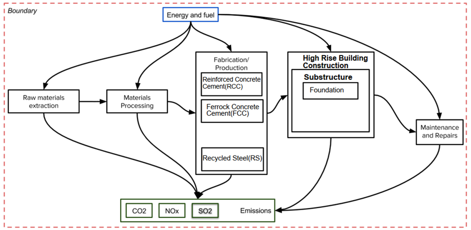
Figure 1. Boundary, Scope and Goal
By choosing a design that emits the fewest CO2, NOx, and SO2 emissions, the LCA assignment aims to reduce the carbon footprint. The following portion of this report goes into more depth about the three design solutions that were chosen for the foundation of a High-Rise Building. The actions taken during a product’s life cycle that have a direct or indirect impact on the objective are included in the scope. Since the objective of this assignment is to reduce carbon footprint, all emission-producing processes—from material extraction to processing and fabrication of materials like Ferrock Concrete Cement(FCC), and Reinforced Concrete Cement(RCC) to actual implementation and creation of the components that form the foundation of the High-Rise Building to maintenance and repair—are taken into consideration.
3.Design Options
We have three different design options for the foundation of the High-Rise Building:
3.1.Isolated Footing
A foundational kind known as an isolated footing is used to support a single column or a small cluster of closely spaced columns. Typically, it comprises of a ground-mounted, rectangular or circular concrete pad that is reinforced with steel bars. Small structures like houses and modest commercial buildings frequently have isolated footings. If the ground is solid, it is also infrequently employed in high-rise buildings.
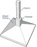
Figure 2. Isolated Footing
3.2.Pile Foundation
A pile foundation is a form of deep foundation that shifts the weight of a structure to a layer of soil or rock that is deeper and more capable. It consists of long, thin columns that are pushed or cast into the ground and constructed of materials like concrete, steel, or wood. They are frequently employed in the construction of offshore projects, large buildings, and bridges.
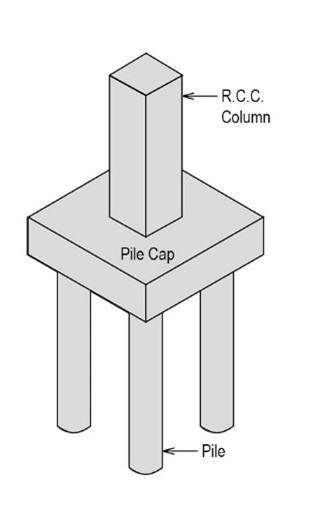
Figure3. Pile Foundation
3.3.Raft Foundation
A raft foundation is a type of shallow foundation that spreads the load of a structure over a wide area, rather than supporting it on individual footings. It is typically made of reinforced concrete and covers a large area, often the entire footprint of the building. The raft foundation is designed to distribute the load evenly across the soil and prevent excessive settling or shifting. It is used primarily in soil conditions that are not suitable for conventional shallow foundations, such as soft or unstable soil. They are commonly used in the construction of large commercial and industrial buildings, bridges, and other structures.
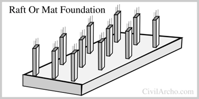
Figure 4. Raft Foundation
- Timetable
The first important factor is Grouting. Grouting is a process used in foundation construction to fill voids, stabilize soils, and transfer loads in and around foundations. It involves injecting a fluid mixture, called grout, into the soil or rock around a foundation. This step is an important process in the sustainability of the foundations and must be repeated every 17 years. Grouting is shown as G in the Timetable.
Periodic maintenance of the foundations is another important factor for the sustainability of the foundations. In order to have sustainable foundations, foundation maintenance is required every 13 years. Basic maintenance periods are marked M on the timetable.
The frequency of reinforcing an isolated footing depends on several factors such as the soil conditions, the type of structure built on the foundation, and the quality of the original construction. Since our structure is a high-rise building, these foundations were laid more solidly. For this reason, it needs to be reinforced and strengthened in every 40 years. It appears as SI in the Timetable and is repeated every 50 years.
The piles are driven into the ground by hammering or drilling until a solid layer of soil or rock is reached. For this reason, this foundation needs to be strengthened every 30 years. It appears as an SP in the Timetable.
The distribution of all the above-mentioned events in the timetable is as follows.
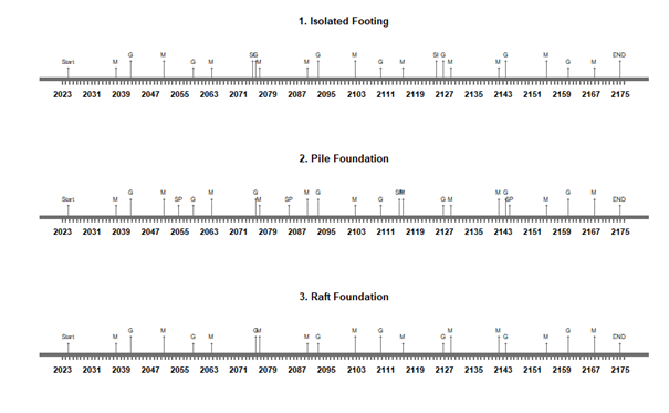
Figure 5. Timetable for Design Options
- Life Cycle Inventory of Different Materials, Performance and Environmental Indicators
Different concrete mixes can be used to create FCC. RCC, which is used for insulated foundations and pile foundations, is made of typical coarse aggregates, whereas FCC is made of fine aggregates; however, the raft foundation is made of recycled aggregate. The amounts are given in kilograms per cubic meter (kg/m3) and represent the weight in kilograms of the required ingredients used to create one m3 of concrete cubes. From the time that the building’s materials are extracted as raw materials until the conclusion of its life cycle, CO2, NOX, and SO2 emissions are what the house emits in terms of quantity.
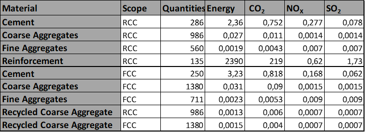
Table 1. Life Cycle Inventory
- Cost Analysis
The cost analysis was done with R studio and the only thing that was taken as a basis while doing this was the amount of material used. The dimensions of the basic design options are entered into the system to find the amount of material.
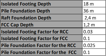
Table 2. Dimensions
Next in Figure 6, the first row represents the results of Energy Consumption, the second row represents the results of CO2 Emission, the 3rd row represents the results of NOX Emission and the 4th row represents the results of SO2 Emission.
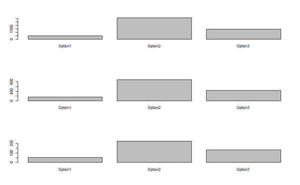
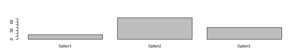
Figure 6
Also, radar plots can be seen here in Figure 7.
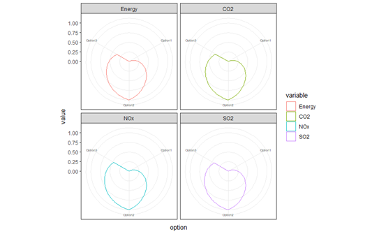
Figure 7.
- MCDM – Analytic hierarchy process (AHP)
The priority of the option decreases with the increasing score or rank on the scale. These numbers are used to generate a, b, c, and d matrices, which compare various design possibilities for a specific price. Additionally, comparisons inside the matrix e are made. Priorities are also given for CO2, energy, NOx, and SO2 in descending order for various costs. Since lowering its carbon footprint is the main goal of this designation, CO2 is given the highest importance.
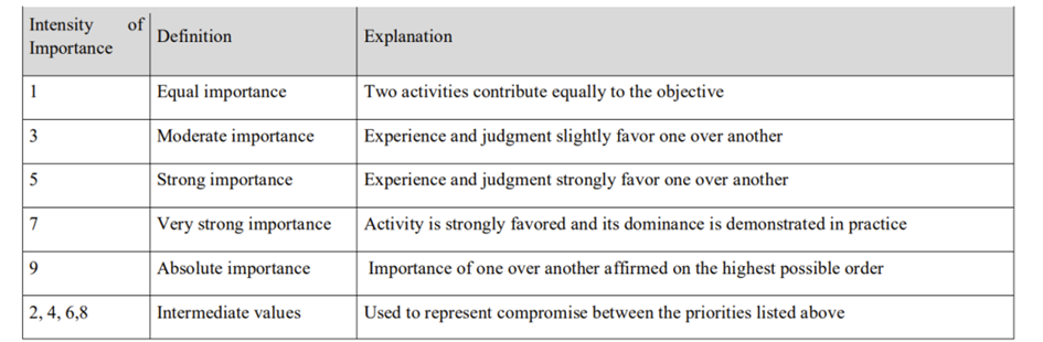
Table 3.
The ranking of the design options by using AHP could be seen in Chart 1.
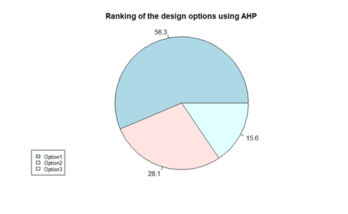
Chart 1.
8.Results
As can be seen in the chart made by AHP, the option with the lowest carbon dioxide emission is the 1st design option.
9.References
Layla, N., Liebe, E., Bodaghi, E., Prajapati, T., Hisham, M. T. M., Abdelaziz, M. B., … & Moyano, G. R. L. (2019). Sustainable construction. Sustainable cities II, 13.
Niveditha, M., Manjunath, Y. M., & Prasanna, S. H. (2020). Ferrock: A carbon negative sustainable concrete. International Journal of Sustainable Construction Engineering and Technology, 11(4), 90-98.
Pınarbaşı, S., & Nasrat, M. S. (2020). A comparative study of former and latest Turkish design guidelines for rolled I-shaped steel flexural members. Journal of the Faculty of Engineering and Architecture of Gazi University, 35(1), 369-385.
Thomas, A., Lombardi, D. R., Hunt, D., & Gaterell, M. (2009, September). Estimating carbon dioxide emissions for aggregate use. In Proceedings of the Institution of Civil Engineers-Engineering Sustainability (Vol. 162, No. 3, pp. 135-144). Thomas Telford Ltd.
Qin, X., & Kaewunruen, S. (2022). Environment-friendly recycled steel fibre reinforced concrete. Construction and Building Materials, 327, 126967.
Life-Cycle Analysis and Multi-Criteria Decision Analysis, A Bridge Example